Controller for oscillator

a controller and oscillator technology, applied in oscillation comparator circuits, oscillation generators, pulse automatic control, etc., can solve problems such as phase noise, deterioration of characteristics, and dependence on the time required for adjustmen

Active Publication Date: 2007-10-25
KK TOSHIBA
View PDF3 Cites 53 Cited by
  • Summary
  • Abstract
  • Description
  • Claims
  • Application Information

AI Technical Summary

Benefits of technology

[0022] According one aspect of the present invention, there is provided: an oscillator controller, comprising a phase frequency detector that compares a reference signal and a frequency-divided signal and outputs a phase difference signal; a charge pump that outputs a phase error signal according to the phase difference signal output from said phase frequency detector; a loop filter that filters the phase error signal output from said charge pump and outputs an oscillation frequency controlling voltage; a voltage-controlled oscillator that has an LC resonator having a coil, a variable capacitor connected to the opposite ends of the coil at the opposite ends thereof, and a capacitor connected in series with a switch between the opposite ends of said variable capacitor, the oscillation frequency of the voltage-controlled oscillator being controlled through adjustment of the capacitance value of said variable capacitor by said oscillation frequency controlling voltage; a frequency divider that divides the frequency of the output of said voltage-controlled oscillator and outputs said frequency-divided signal; a first counter that counts the number of waves of said reference signal to a desired number and outputs a first flag signal; a second counter that counts the number of waves of said frequency-divided signal to said desired number and outputs a second flag signal; a first comparator that compares said first flag signal and said second flag signal and outputs a frequency comparison signal; and a control circuit that controls said voltage-controlled oscillator, said first counter, said second counter and said frequency divider by outputting signals thereto.
[0023] According another aspect of the present invention, there is provided: an oscillator controller, comprising a phase frequency detector that compares a reference signal and a frequency-divided signal and outputs a phase difference signal; a charge pump that outputs a phase error signal according to the phase difference signal output from said phase frequency detector; a loop filter that filters the phase error signal output from said charge pump and outputs an oscillation frequency controlling voltage; a voltage-controlled oscillator whose oscillation frequency is controlled by said oscillation frequency controlling voltage; a frequency divider having a prescaler that counts the number of waves of an oscillation signal output from said voltage-controlled oscillator and a pulse swallow counter that receives the output of the prescaler, controls the frequency division ratio of said prescaler, and outputs said fr

Problems solved by technology

As a result, the sensitivity to the noise on the controlling voltage increases, causing deteriorations of characteristics, such as phase noise and spur.
The oscillation frequency adjustment method of the conventional voltage-controlled oscillator has a p

Method used


Image

  • Controller for oscillator
  • Controller for oscillator
  • Controller for oscillator

Examples


embodiment 1

[0046] With regard to an embodiment 1, there will be described a case where the frequency of a digital control PLL is low, and a signal with a sufficient amplitude can be extracted.

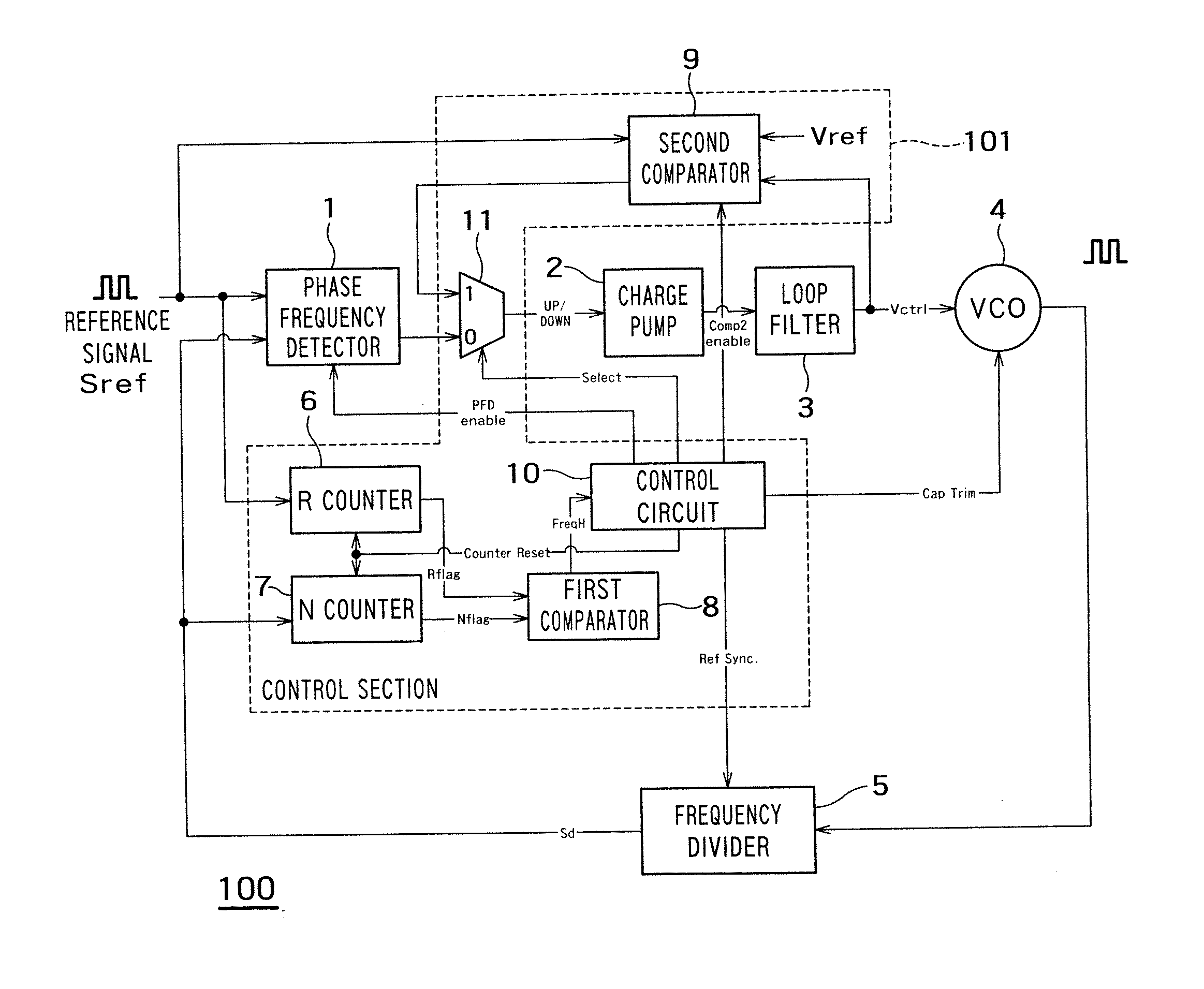
[0047]FIG. 1 is a diagram showing essential parts of an oscillator controller 100 according to the embodiment 1 of the present invention.

[0048] As shown in FIG. 1, the oscillator controller 100 has a phase frequency detector 1 that compares a reference signal “Sref” and a frequency-divided signal “Sd” and outputs a phase difference signal, a charge pump 2 that outputs a phase error signal based on the phase difference signal output from the phase frequency detector 1, and a loop filter 3 that filters the phase error signal output from the charge pump and outputs an oscillation frequency controlling voltage “Vctrl”.

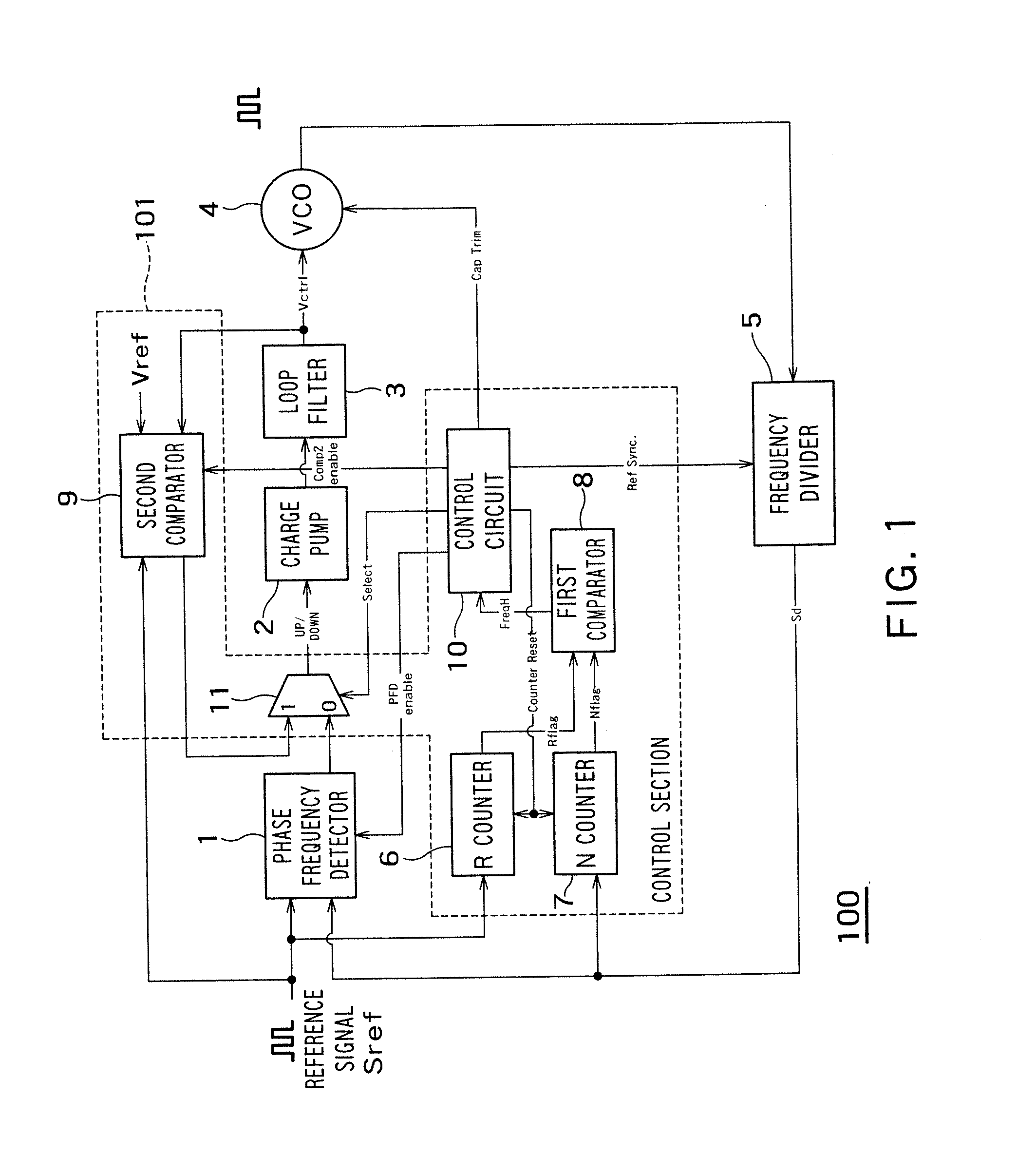
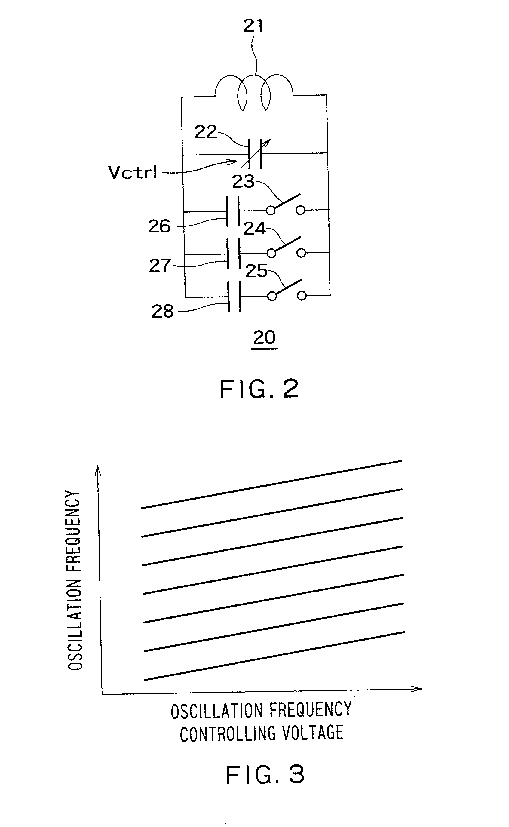
[0049] Furthermore, the oscillator controller 100 has a voltage-controlled oscillator 4 which has an LC resonator and whose oscillation frequency is controlled through adjustment of the capac...

embodiment 2

[0086] With regard to the embodiment 1, there has been described a case where the frequency of a digital control PLL is low, and a signal with a sufficient amplitude can be extracted. In the following, there will be described a case where the frequency of the PLL is high, and the frequency divider has a prescaler and a pulse swallow counter.

[0087]FIG. 10 is a circuit diagram showing a configuration of essential parts of an oscillator controller 200 according to an embodiment 2 of the present invention, which is an aspect of the present invention. In this drawing, the same reference numerals as those in the embodiment 1 denote the same parts as those in the embodiment 1.

[0088] As shown in FIG. 10, a frequency divider 205 of the oscillator controller 200 has a prescaler 12 that counts the number of waves of the oscillation signal output from a voltage-controlled oscillator 4 and a pulse swallow counter 13 that receives the output “Pres Sig” of the prescaler 12, outputs a control sig...

embodiment 3

[0093] In the configurations described above with regard to the embodiments 1 and 2, the second comparator and the multiplexer are used to fix the oscillation frequency controlling voltage at the reference voltage. With regard to an embodiment 3, there will be described another configuration for fixing the oscillation frequency controlling voltage at the reference voltage.

[0094]FIG. 11 is a diagram showing a configuration of essential parts of an oscillator controller 300 according to the embodiment 3, which is an aspect of the present invention. In this drawing, the same reference numerals as those in the embodiments 1 and 2 denote the same parts as those in the embodiments 1 and 2. In FIG. 11, illustration of the sigma delta modulator is omitted.

[0095] As shown in FIG. 11, the oscillator controller 300 has a switch circuit 15 provided between a loop filter 3 and a voltage-controlled oscillator 4, instead of the second comparator and the multiplexer.

[0096] The switch circuit 15 ...


PUM


Abstract

An oscillator controller, has a phase frequency detector that compares a reference signal and a frequency-divided signal and outputs a phase difference signal; a charge pump that outputs a phase error signal according to the phase difference signal output from said phase frequency detector; a loop filter that filters the phase error signal output from said charge pump and outputs an oscillation frequency controlling voltage; a voltage-controlled oscillator that has an LC resonator having a coil, a variable capacitor connected to the opposite ends of the coil at the opposite ends thereof, and a capacitor connected in series with a switch between the opposite ends of said variable capacitor, the oscillation frequency of the voltage-controlled oscillator being controlled through adjustment of the capacitance value of said variable capacitor by said oscillation frequency controlling voltage; a frequency divider that divides the frequency of the output of said voltage-controlled oscillator and outputs said frequency-divided signal; a first counter that counts the number of waves of said reference signal to a desired number and outputs a first flag signal; a second counter that counts the number of waves of said frequency-divided signal to said desired number and outputs a second flag signal; a first comparator that compares said first flag signal and said second flag signal and outputs a frequency comparison signal; and a control circuit that controls said voltage-controlled oscillator, said first counter, said second counter and said frequency divider by outputting signals thereto.

Description

CROSS-REFERENCE TO RELATED APPLICATION [0001] This application is based upon and claims the benefit of priority from the prior Japanese Patent Application No. 2006-115461, filed on Apr. 19, 2006, the entire contents of which are incorporated herein by reference. BACKGROUND OF THE INVENTION [0002] 1. Field of the Invention [0003] The present invention relates to an oscillator controller incorporating a voltage-controlled oscillator that outputs an oscillation signal at a desired oscillation frequency. [0004] 2. Background Art [0005] Recently, for example, in the field of mobile communication, the market of which is rapidly growing, there is an increasing demand that a voltage-controlled oscillator (VCO) be mounted on each mobile communication terminal (see Japanese Patent Laid-Open No. 2006-504352, for example). [0006] The voltage-controlled oscillator is capable of changing the oscillation frequency according to an oscillation frequency controlling voltage. [0007] However, recently,...

Claims


Application Information

Patent Timeline
IPC IPC(8): H03B5/08
CPCH03D13/004H03L7/087H03L7/099H03L2207/06H03L7/10H03L7/193H03L7/1976H03L7/0995
Inventor KOBAYASHI, HIROYUKIKOUSAI, SHOUHEI
Owner KK TOSHIBA
Why Eureka
Try Eureka