Camera Module

a camera module and camera technology, applied in the field of small and slim camera modules, can solve the problems of enlargement of the apparatus, mechanical attachment error of two cameras, and difference in correct distance calculated based on parallax, etc., and achieve the effect of small and low-cost camera modules and simple configuration

Active Publication Date: 2007-10-25
PANASONIC INTELLECTUAL PROPERTY CORP OF AMERICA
View PDF5 Cites 47 Cited by
  • Summary
  • Abstract
  • Description
  • Claims
  • Application Information

AI Technical Summary

Benefits of technology

[0015] According to a camera module of the present invention, the distance to an object can be measured by triangulation, and an object image can be captured. Thus, the shape recognition of an object and the measurement of the distance to the object can be performed simultaneously.
[0016] Furthermore, since a plurality of lenses are integrated as a lens module, a plurality of independent cameras are not required. Thus, with a simple configuration, a small and low-cost camera module can be realized.

Problems solved by technology

However, in this stereo camera apparatus, a mechanical attachment error of two cameras exists.
In particular, the displacement in the horizontal direction causes an error in the parallax obtained based on two images, and consequently, the distance calculated based on the parallax differs from a correct distance.
This causes problems such as the enlargement of an apparatus, the degradation in a layout property, and the increase in cost.
Furthermore, even in the case of enhancing the recognition rate at night, two cameras, i.e., a visible light camera and an infrared camera are required, which causes problems such as the enlargement of an apparatus, the degradation in a layout property, and the increase in cost.
Thus, optical systems are required independently for measuring a distance and capturing an image, which increases the number of components and assembly man-hour to increase cost, and enlarges an apparatus.

Method used


Image

  • Camera Module
  • Camera Module
  • Camera Module

Examples


embodiment 1

[0042] Hereinafter, Embodiment 1 of the present invention will be described with reference to the drawings.

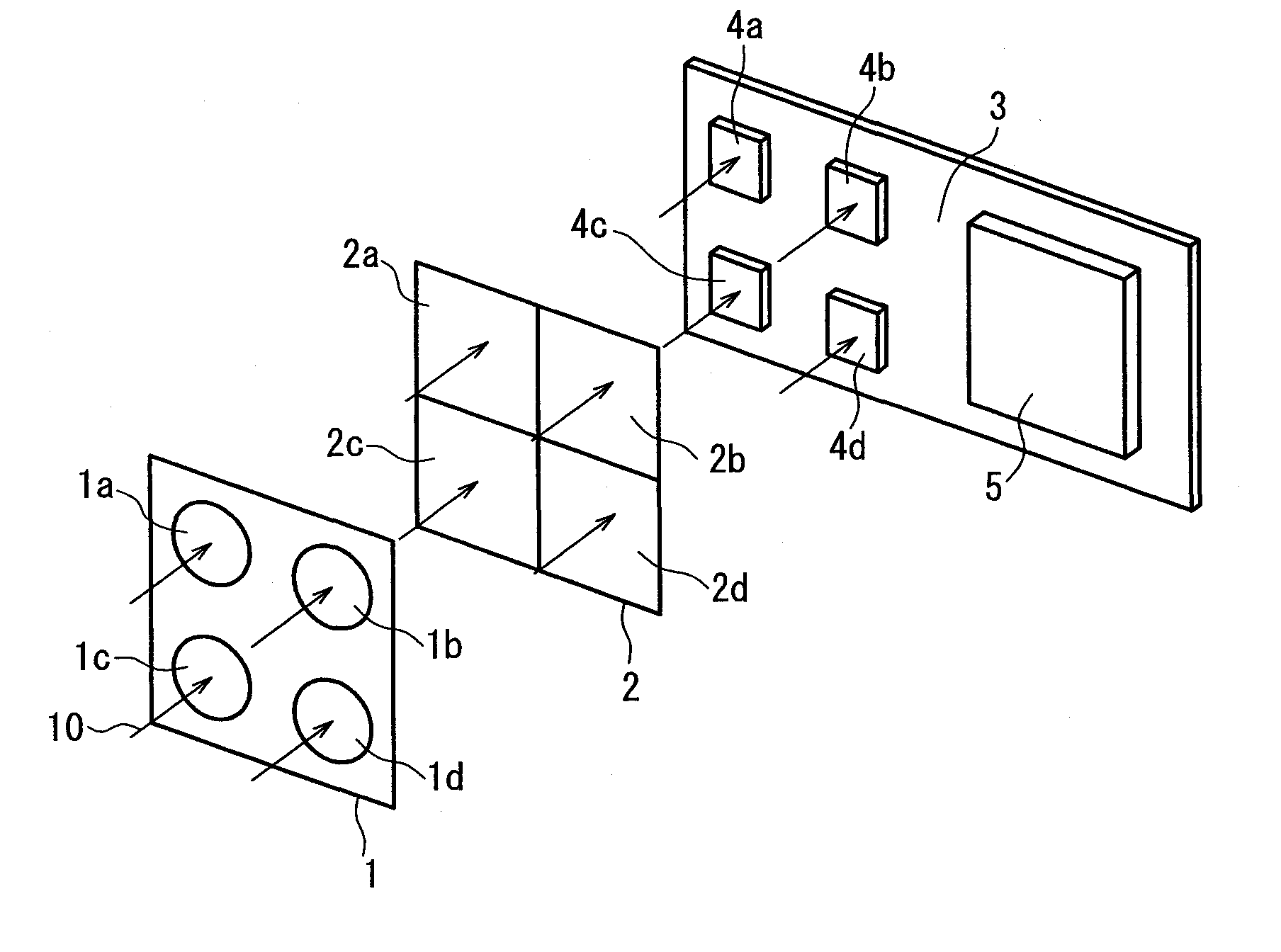
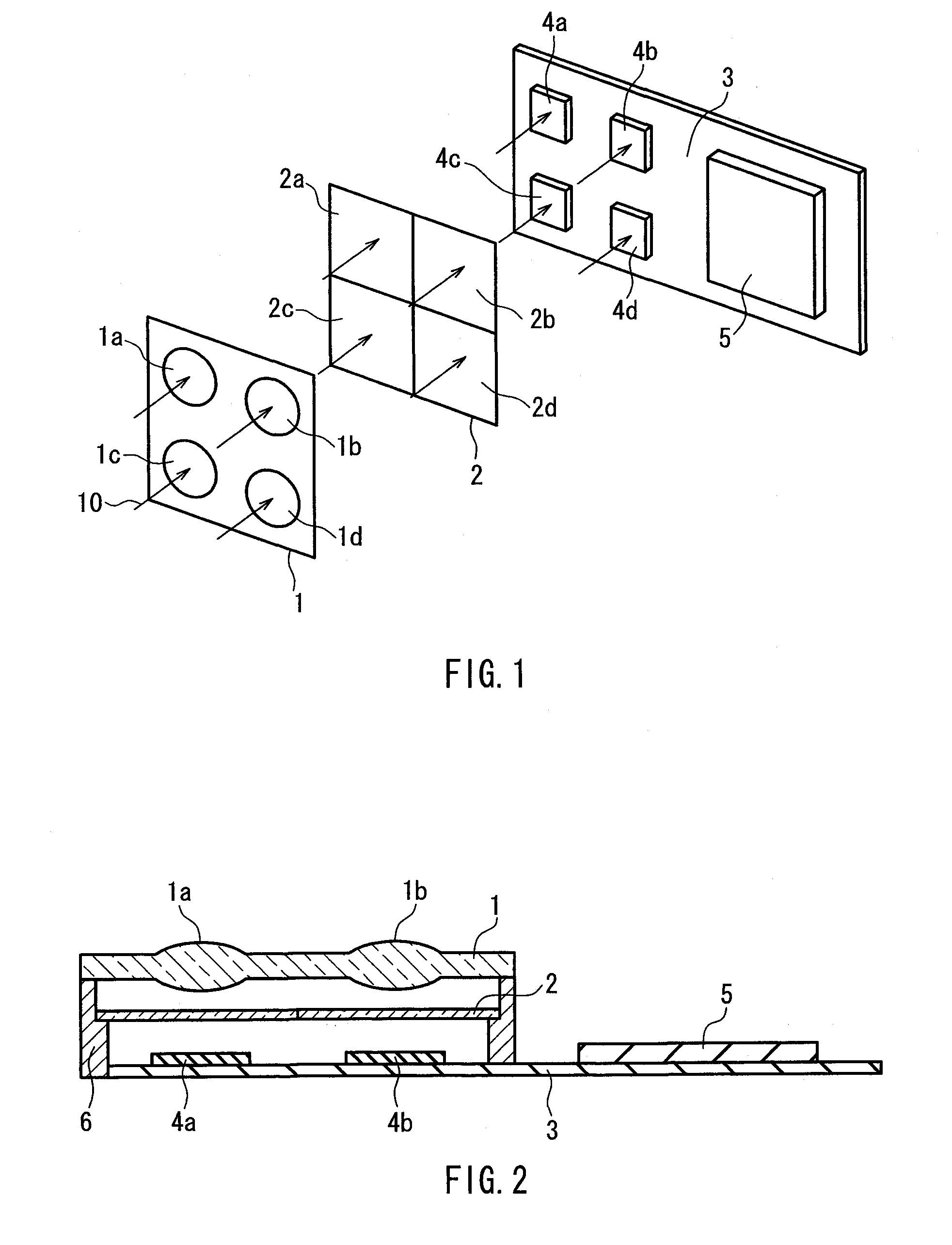
[0043]FIG. 1 is an exploded perspective view of a camera module of Embodiment 1.

[0044] A camera module of the present embodiment includes a lens module 1, an optical filter module 2, and a substrate 3 in this order from an object side. On the substrate 3, imaging devices 4a-4d, and a signal processing portion 5 composed of a digital signal processor (DSP) and the like are mounted. Arrows 10 represent light beams from the object.

[0045]FIG. 2 is a cross-sectional view of the camera module of the present embodiment along a direction parallel to an optical axis of the lens module 1. In FIG. 2, reference numeral 6 denotes a fixing stage for supporting and fixing the lens module 1 and the optical filter module 2 with respect to the substrate 3.

[0046] In FIG. 1, the optical filter module 2 has four wavelength selection regions 2a-2d. The wavelength selection regions 2a, 2d placed ...

embodiment 2

[0066] Hereinafter, Embodiment 2 of the present invention will be described with reference to the drawings.

[0067] The entire configuration of a camera module of Embodiment 2 is substantially the same as that of the camera module of Embodiment 1 shown in FIGS. 1 and 2, and Embodiment 2 is different from Embodiment 1 in terms of individual constituent elements of the camera module. Hereinafter, Embodiment 2 will be described mainly based on the difference from Embodiment 1.

[0068]FIG. 4 is a conceptual view of an optical filter module 21 used in the camera module according to Embodiment 2. In FIG. 4, wavelength selection regions 21a, 21d placed at positions diagonal to each other are respectively composed of an infrared optical filter for selectively transmitting infrared light among light from an object, and in wavelength selection regions 21b, 21c placed at positions diagonal to each other, red optical filters 21R, green optical filters 21G, and blue optical filters 21B for transmi...

embodiment 3

[0077] Hereinafter, Embodiment 3 of the present invention will be described with reference to the drawings.

[0078] The entire configuration of the camera module of Embodiment 3 is substantially the same as that of the camera module of Embodiment 1 shown in FIGS. 1 and 2, and Embodiment 3 is different from Embodiment 1 in terms of individual constituent elements of the camera module. Hereinafter, Embodiment 3 will be described mainly based on the difference from Embodiment 1.

[0079]FIG. 6 is a perspective view of an optical filter module 31 used in the camera module according to Embodiment 3. In FIG. 6, wavelength selection regions 31b, 31c placed at positions diagonal to each other are respectively composed of a green optical filter for selectively transmitting green light among light from an object, a wavelength selection region 31a is composed of a red optical filter for selectively transmitting red light among the light from the object, and a wavelength selection region 31d is co...


PUM


Abstract

A plurality of lenses (1a-1d) of a lens module (1), a plurality of wavelength selection regions (2a-2d) each having at least one optical filter, and a plurality of imaging regions (4a-4d) are placed in one-to-one correspondence. At least two of the plurality of wavelength selection regions transmit light in at least one wavelength band among infrared light, red light, green light, and blue light. The distance to an object is calculated based on at least two pieces of image information outputted respectively from at least two imaging regions respectively corresponding to the at least two wavelength selection regions. Furthermore, a camera module outputs an image signal based on image information outputted from at least one of the plurality of imaging regions. This can realize a small and low-cost camera module capable of measuring the distance to an object and capturing the object.

Description

TECHNICAL FIELD [0001] The present invention relates to a small and slim camera module capable of measuring the distance to an object. BACKGROUND ART [0002] Conventionally, a stereo camera apparatus capable of being mounted on an automobile is known, which captures an object by a stereo camera equipped with two cameras, and arithmetically manipulates the obtained image information to calculate the distance to the object (see JP 5(1993)-265547 A). The distance calculation in the stereo camera apparatus is performed as follows. Using triangulation, which is one of the three-dimensional measurement techniques, a pixel block having a correlation with a pixel block in an image obtained by one camera is searched for and specified in an image obtained by the other camera. Then, the distance to an object is calculated based on the parallax between both the pixel blocks, i.e., the relative displacement amount of the respective pixel blocks in two images (stereo images). [0003] However, in th...

Claims


Application Information

Patent Timeline
Patent Type & Authority Applications(United States)
IPC IPC(8): G01C3/06B60R1/00G01C3/08G02B3/00G02B5/20G02B7/30
CPCB60R1/00B60R2300/106B60R2300/107B60R2300/108B60R2300/8033B60R2300/8093H04N9/09G02B3/0006G02B5/201H04N5/2254H04N5/2257H04N5/332G01C3/085H04N23/57H04N23/55H04N23/11H04N23/13H04N23/843
Inventor TAMAKI, SATOSHINAGASHIMA, MICHIYOSHI
Owner PANASONIC INTELLECTUAL PROPERTY CORP OF AMERICA
Why Eureka
Try Eureka