Flexible capacitive sensor

a capacitive sensor and flexible technology, applied in the direction of fluid pressure measurement using inductance variation, pulse technique, instruments, etc., can solve the problems of not teaching a system, capacitive coupling may not be well suited to quantitatively measuring applied pressure or proximity, and cannot work if, etc., to achieve large capacitive sensor array, large fabric, and quick and easy connection

Inactive Publication Date: 2007-10-25
MILLIKEN & CO
View PDF51 Cites 99 Cited by
  • Summary
  • Abstract
  • Description
  • Claims
  • Application Information

AI Technical Summary

Benefits of technology

[0010] One advantage of the present invention is the manner in which the components, namely, the active layer, the dielectric layer, and the reference layer can be assembled to form the present capacitive sensor in a large-scale manufacturing process. Coating, gluing, and screen printing operations can be easily automated. Such operations can make a very large capacitive sensor array or a large fabric from which individual sensors or sensor arrays can be cut.
[0011] Another important feature of the present invention is compatibility with the use of penetration connectors for quickly and easily connecting traces and the reference plate to a capacitance meter (an electrical measurement system) so that electrical signals can be applied or measured from the present sensor without the need for customized electrical connections.
[0012] Still another feature of the present invention is the use of capacitance rather than resistance for sensing contact. Resistance typically requires the two conductive surfaces to touch; capacita

Problems solved by technology

Because these systems often require direct contact between the person and the sensing system they may not work if, for example the person is wearing a glove.
Additionally, capacitive coupling may not be well suited to quantitatively measuring the applied pressure or proximity, but are ca

Method used


Image

  • Flexible capacitive sensor
  • Flexible capacitive sensor
  • Flexible capacitive sensor

Examples


Embodiment Construction

[0029] The flexible capacitive sensor experiences a change in capacitance upon the application of force sufficient to compress the sensor. The amount of applied force, up to a point, is related to the extent of the change in capacitance. In an alternate embodiment, the resistance is also measured to determine the location of user interaction on the sensor. A capacitance meter monitors the present flexible capacitive sensor to determine whether there has been a change in capacitance and the extent of that change.

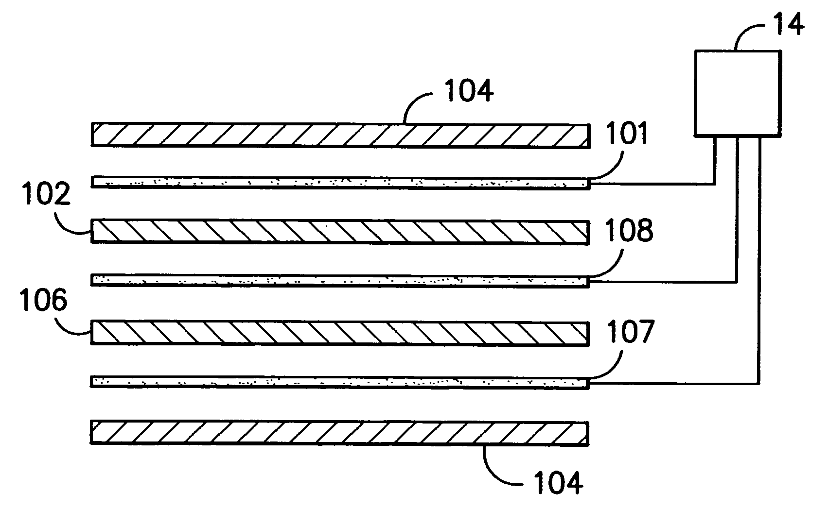
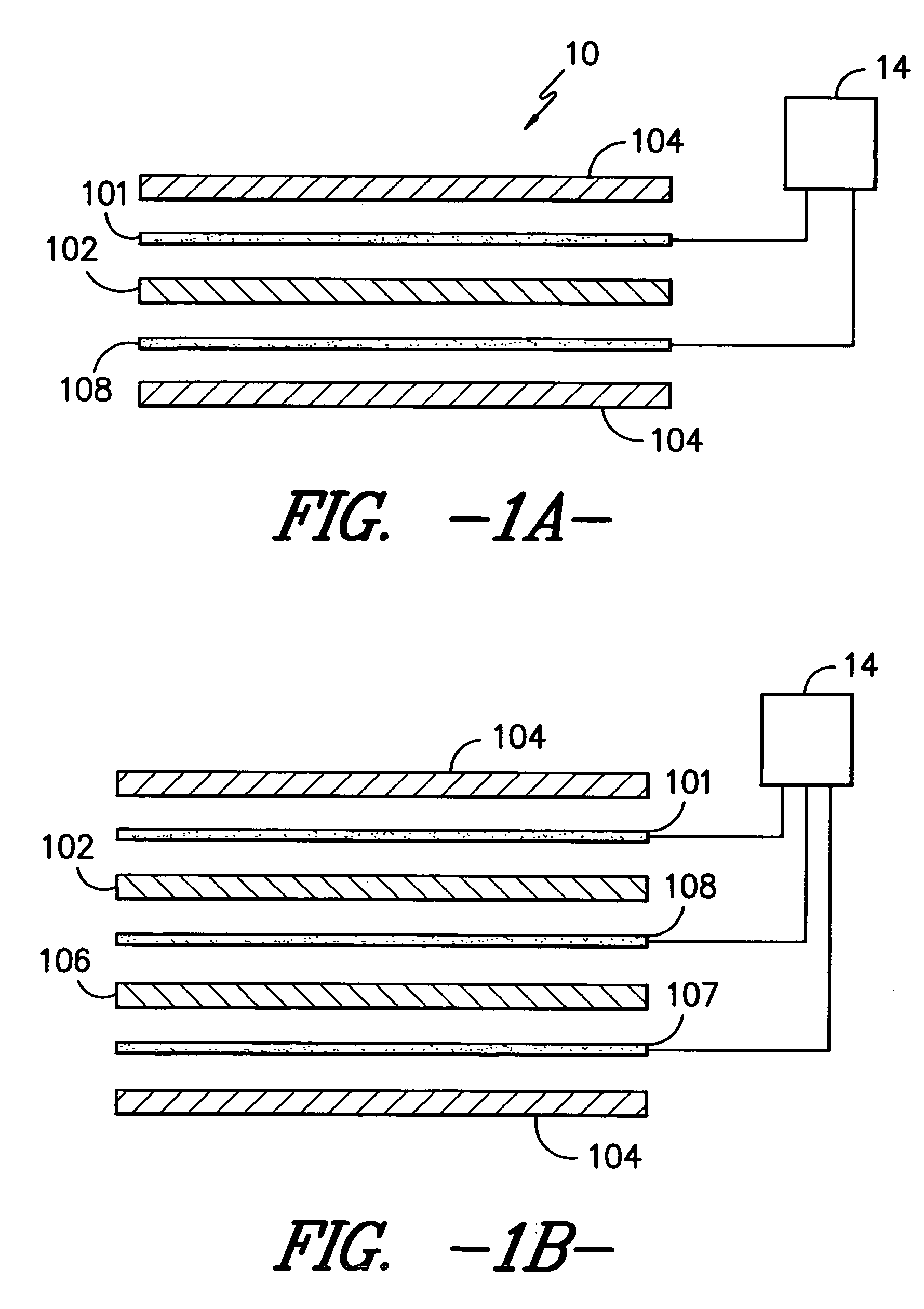
[0030] Referring now to FIG. 1A shows one embodiment of a capacitive pressure sensor 10 which generally includes a first conductive layer 101, a flexible, resilient dielectric layer 102, and a second conductive layer 108. The capacitive pressure sensor 10 may also include a protective layer 104 on one or both sides of the sensor 10. The first conductive layer 101 and the second conductive layer 108 are electrically connected to the capacitance meter 14.

[0031] In one embodim...


PUM

PropertyMeasurementUnit
Angleaaaaaaaaaa
Angleaaaaaaaaaa
Electrical resistanceaaaaaaaaaa

Abstract

The invention relates to a flexible, resilient capacitive sensor suitable for large-scale manufacturing. The sensor comprises a dielectric, an electrically conductive layer on the first side of the dielectric layer, an electrically conductive layer on a second side of the dielectric layer, and a capacitance meter electrically connected to the two conductive layers to detect changes in capacitance upon application of a force to the detector. The conductive layers are configured to determine the position of the applied force. The sensor may be shielded to reduce the effects of outside interference.

Description

TECHNICAL FIELD [0001] This invention relates to a flexible capacitive sensor. More particularly, the invention relates to a capacitive sensor suitable for large-scale manufacturing, that is both physically flexible and flexible in its applications, and that senses incremental changes in pressure based on the changes in the capacitance of the sensor. BACKGROUND [0002] Sensors, as the term is used here, refer to systems that react to a change in the environment. Pressure sensors react to an applied force or pressure using a variety of physical principles. Optical sensors change their optical properties under applied force. Similarly, electrically resistive, or simply resistive, sensors have an electrical resistance that changes under applied force. Piezoresistive sensors measure the change in electrical resistance of a piezoresistive material as pressure is applied. [0003] Capacitive sensors change capacitance. This can be in response to an applied force; it can also be in response t...

Claims


Application Information

Patent Timeline
IPC IPC(8): B32B3/00
CPCG01L1/146G06F3/044Y10T428/24917H03K2017/9602H03K2217/96076H03K17/9622G06F3/0445G06F3/0446G06F3/0448
Inventor DEANGELIS, ALFRED R.WILSON, D. BRUCEMAZZEO, BRIAN A.
Owner MILLIKEN & CO
Why Eureka
Try Eureka