Exhaust Gas Control Apparatus for Internal Combustion Engine

a control apparatus and exhaust gas technology, applied in engine controllers, electric control, machines/engines, etc., can solve the problems of insufficient increase of exhaust gas temperature by downstream oxidation catalysts, ineffective oxidation of particulate matter, and excessive space velocity

Inactive Publication Date: 2007-11-01
TOYOTA JIDOSHA KK
View PDF9 Cites 3 Cited by
  • Summary
  • Abstract
  • Description
  • Claims
  • Application Information

AI Technical Summary

Benefits of technology

[0006] It is an object of the invention to provide an exhaust gas control apparatus for an internal combustion engine, which makes it possible to increase a region where a filter recovery process can be performed such that the filter recovery process can also be performed at lower loads of the internal combustion engine.
[0008] When fuel (HC) required for the filter recovery process is supplied by the fuel supply means, the temperature of the exhaust gas flowing in the upstream side oxidation catalyst is increased due to an oxidation reaction of the HC, and the exhaust gas whose temperature has been increased flows in the downstream side oxidation catalyst provided downstream of the upstream side oxidation catalyst. In this case, when the capacity of the upstream side oxidation catalyst is made excessively small (the space velocity is made excessively high), even if the fuel supply amount is increased, the exhaust gas temperature is increased by only an amount corresponding to the small capacity of the upstream side oxidation catalyst. Therefore, the exhaust gas temperature cannot be sufficiently increased by the downstream side oxidation catalyst. As a result, particulate matter may not be effectively oxidized and removed. According to the aspect of invention, however, the capacity of the upstream side oxidation catalyst is appropriately set such that the space velocity (SV) during idling of the internal combustion engine is equal to or lower than 175,000 (l / h). It is therefore possible to increase the region where the filter recovery process can be performed such that the filter recovery process can also be performed at lower loads of the internal combustion engine, while minimizing the capacity of the upstream side oxidation catalyst. Note that the space velocity in the aspect of the invention is a ratio of an amount of gas flowing in the catalyst per hour (h) to the capacity of the catalyst.
[0009] In the aspect of the invention, the upstream side oxidation catalyst is provided downstream of the turbine of the turbocharger. It is therefore possible to avoid problems which may be caused by providing the upstream side oxidation catalyst upstream of the turbine, for example, deterioration of supercharging response due to insufficiency of an amount of heat supplied to the turbine, and heat deterioration of the catalyst due to exposure of the catalyst to a high temperature (equal to or higher than 700° C.).
[0011] With the above-mentioned exhaust gas control apparatus, it is possible to increase the region where the filter recovery process can be performed such that the filter recovery process can also be performed at lower loads of the internal combustion engine. Note that the capacity of the upstream side oxidation catalyst may be one-thirtieth to one-fifth of a capacity of the downstream side oxidation catalyst.

Problems solved by technology

In this case, when the capacity of the upstream side oxidation catalyst is made excessively small (the space velocity is made excessively high), even if the fuel supply amount is increased, the exhaust gas temperature is increased by only an amount corresponding to the small capacity of the upstream side oxidation catalyst.
Therefore, the exhaust gas temperature cannot be sufficiently increased by the downstream side oxidation catalyst.
As a result, particulate matter may not be effectively oxidized and removed.

Method used


Image

  • Exhaust Gas Control Apparatus for Internal Combustion Engine
  • Exhaust Gas Control Apparatus for Internal Combustion Engine
  • Exhaust Gas Control Apparatus for Internal Combustion Engine

Examples


Embodiment Construction

[0018] In the following description, the present invention will be described in more detail in terms of exemplary embodiments.

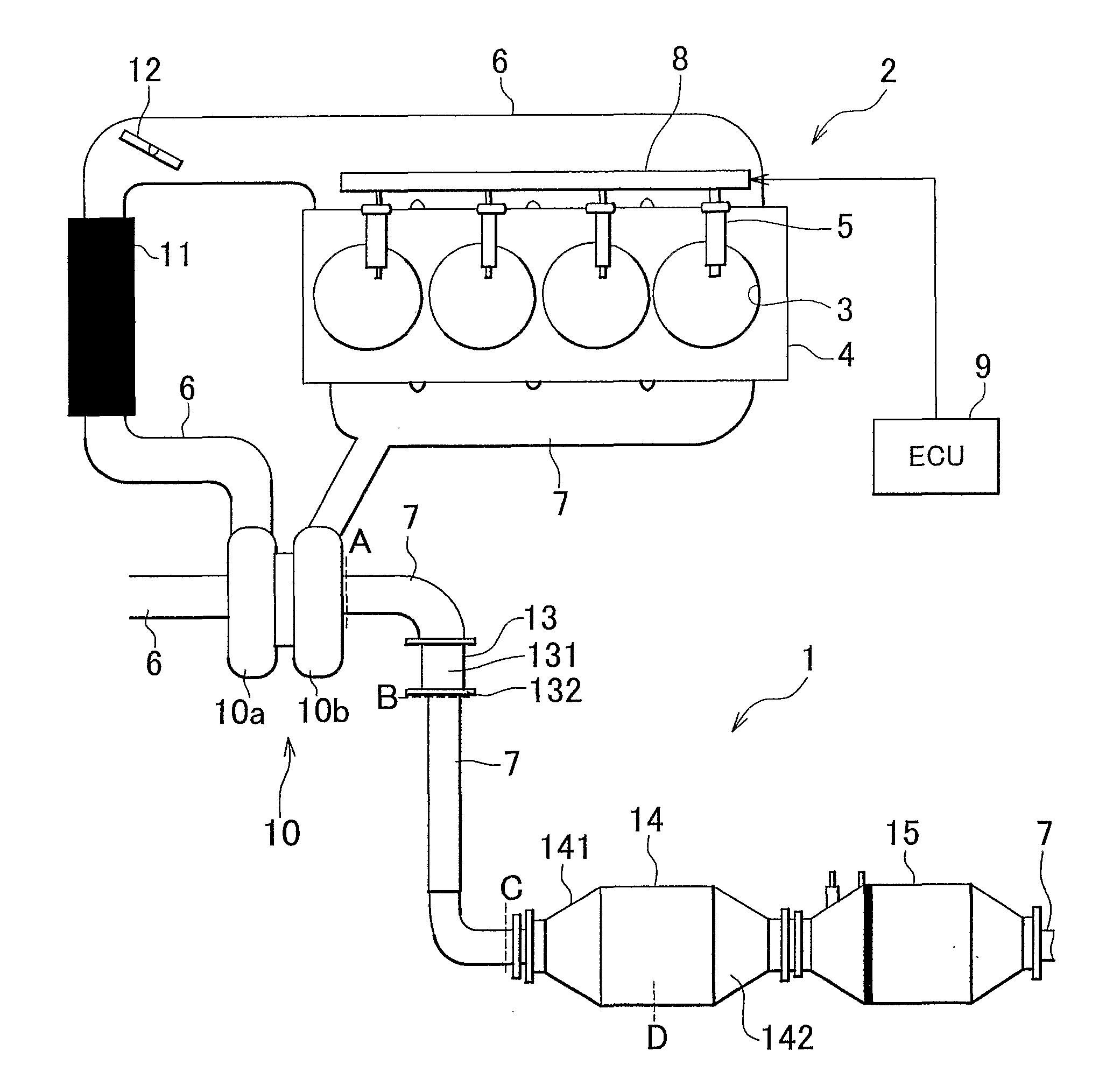
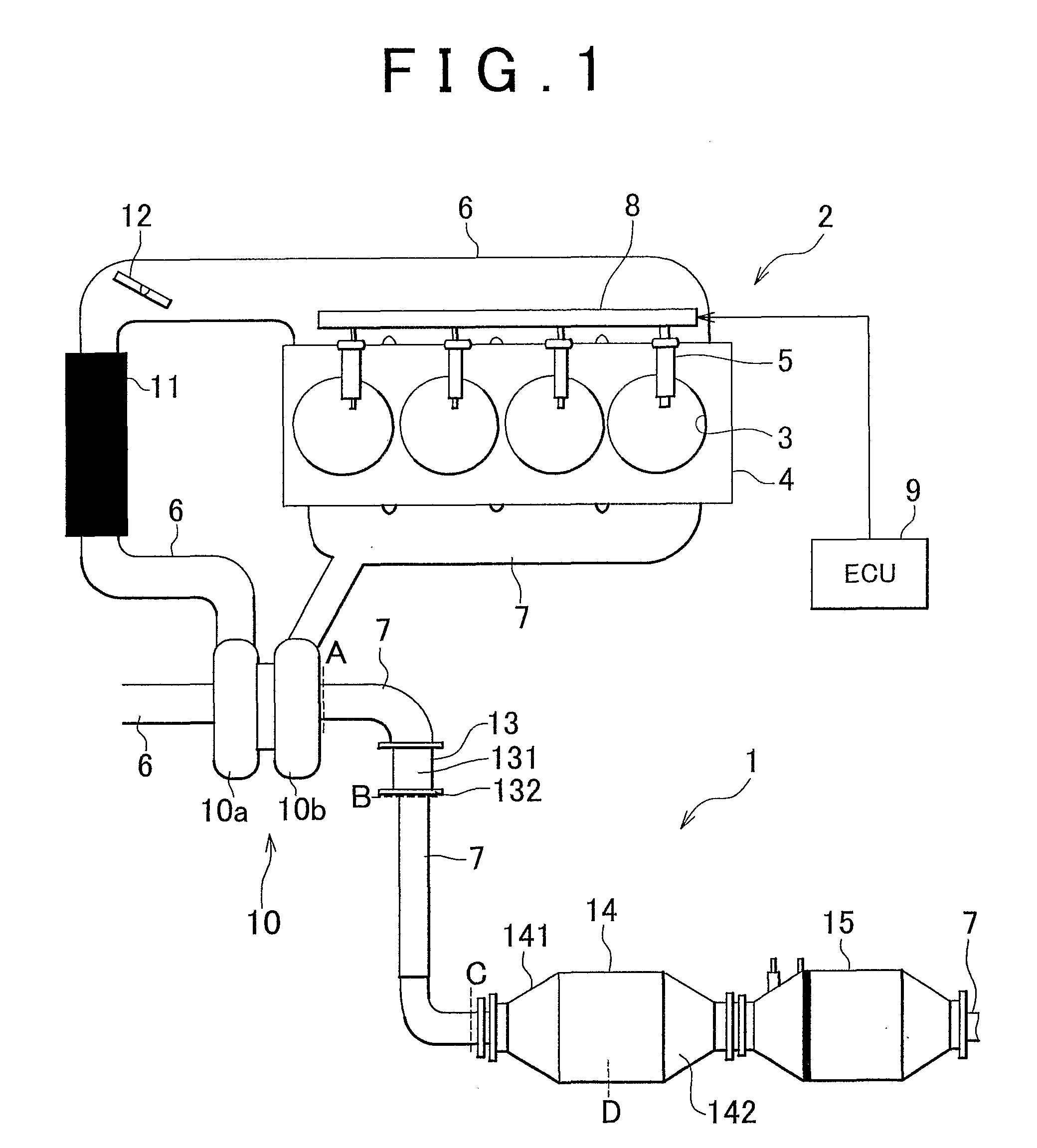
[0019]FIG. 1 is a view schematically showing a diesel engine (hereinafter, simply referred to as an “engine”) 2 to which an exhaust gas control apparatus 1 according to the invention is applied. As shown in FIG. 1, the engine 2 is a reciprocating four-cylinder engine. The engine 2 includes a cylinder block 4 in which cylinders 3 are formed, injectors 5 which are provided for the respective cylinders 3, and an intake passage 6 and an exhaust passage 7 which are connected to the cylinder block 4. The injectors 5 are connected to a common rail 8, and inject fuel, which has been supplied to the common rail 8 under pressure by a pressure pump (not shown) and then stored in the common rail 8, to the respective cylinders 3. An engine control unit (ECU) 9 controls an amount of fuel injected by the injectors 5, fuel injection timing, and the like.

[0020] A compressor...


PUM


Abstract

An exhaust gas control apparatus (1) according to the invention is applied to a diesel engine (2) including a turbocharger (10). The exhaust gas control apparatus (1) includes an upstream side oxidation catalyst (13) which is provided down-stream of a turbine (10b) of the turbocharger (10); a downstream side oxidation catalyst (14) which is provided downstream of the upstream side oxidation catalyst (13); a particulate filter (15) which is provided downstream of the downstream side oxidation catalyst (13); and an injector (5) which supplies fuel required for a filter recovery process for oxidizing and removing particulate matter accumulated in the particulate filter (15). The capacity of the upstream side oxidation catalyst (13) is set such that a space velocity (SV) during idling of the internal combustion engine (2) is equal to or lower than 175,000 (l / h).

Description

BACKGROUND OF THE INVENTION [0001] 1. Field of the Invention [0002] The invention relates to an exhaust gas control apparatus for an internal combustion engine. [0003] 2. Description of Related Art [0004] There is a known exhaust gas control apparatus for an internal combustion engine, which includes an oxidation catalyst and a particulate filter that is provided downstream of the oxidation catalyst and that traps particulate matter in exhaust gas, and which supplies fuel (HC) from a position upstream of the oxidation catalyst, thereby oxidizing and removing the particulate matter trapped in the particulate filter. Such a technology is disclosed in, for example, Japanese Patent Application Publication No. JP(A) 60-43113. There is another known exhaust gas control apparatus for an internal combustion engine. In this exhaust gas control apparatus, a first oxidation catalyst, which has a capacity smaller than that of a second oxidation catalyst that oxidizes the particulate matter, is ...

Claims


Application Information

Patent Timeline
Patent Type & Authority Applications(United States)
IPC IPC(8): F01N3/00
CPCF01N3/035F01N13/009F02D41/086F02D41/029
Inventor HASHIZUME, TAKESHIGOTOU, ISAMUTOMINAGA, HIROYUKI
Owner TOYOTA JIDOSHA KK
Why Eureka
Try Eureka