Windshield removal assembly, method and blade for same

a technology for removing parts and windshields, which is applied in the direction of metal-working hand tools, metal working apparatuses, manufacturing tools, etc., can solve the problems of difficult cutting with tools, difficult to penetrate, and difficult to remove urethane beds, etc., and achieves sufficient rigidity and lateral flexibility. , the effect of sufficient rigidity

Inactive Publication Date: 2007-11-01
CRYSTAL GLASS CANADA
View PDF41 Cites 5 Cited by
  • Summary
  • Abstract
  • Description
  • Claims
  • Application Information

AI Technical Summary

Benefits of technology

[0035] vi. sufficient rigidity to cut the urethane bed when reciprocated, and sufficient lateral flexibility to conform to the curved surface of the windshield when pressed there against.

Problems solved by technology

The urethane bed is hard and tough and not easily penetrated.
In use, these tools were characterized by several problems.
More particularly: Cutting with them was slow.
The depth and width of the cut were small, requiring a great many cuts to complete the job.
Using the prior art assemblies was laborious.
It was common to crack the glass when first penetrating the bed.
This could leave broken glass on the dash and elsewhere, which was undesirable.
This meant that at the corners, where the bed width was greatest, it would take prolonged cutting to complete severing the bed.
In the course of hand cutting the corners, the installer would commonly press hard with his head against the windshield to assist his cutting—this was known to lead to neck injuries.
This was undesirable as the newly extruded bead would in part reproduce this underlying irregularity and the new windshield would then not seat flush against the bed surface.
This could lead to a poor seal and subsequent leaking.
The electric motor-driven tools of the prior art were generally bulky and difficult to work with in confined space, such as the apex between the vehicle dashboard and the inside surface of the windshield.
The prior art blades were fragile and expensive—breakage was a problem.
After the cut was complete, the cut surface needed to be carefully washed to remove soap, as it was detrimental to getting a good bond when new urethane was laid on to the old bed.
While the above Ogston assembly was a marked improvement over many of the other prior art devices, it presented its own unique issues, as follows: The sharp corner edges at the front end of the blade could cause damage to either or both of the pinch weld of the vehicle holding the windshield, or to the dashboard or upholstery of the vehicle.
Penetration of the urethane bed, particularly at the corners where the bed is deepest, was sometimes still difficult.
Cutting around the corners of the windshield presented some difficulty, with the sharp corners limiting movement around the corner.
While the wider blade made the operation much faster than with the prior art designs, it still took several minutes to remove the windshield.
The air gun, while suitable for some applications, did not meet all customer needs.
As well, the “offset” mounting of the blade is not believed to allow the blade to be elongated without breakage at the stress point, as described above.

Method used


Image

  • Windshield removal assembly, method and blade for same
  • Windshield removal assembly, method and blade for same
  • Windshield removal assembly, method and blade for same

Examples


Embodiment Construction

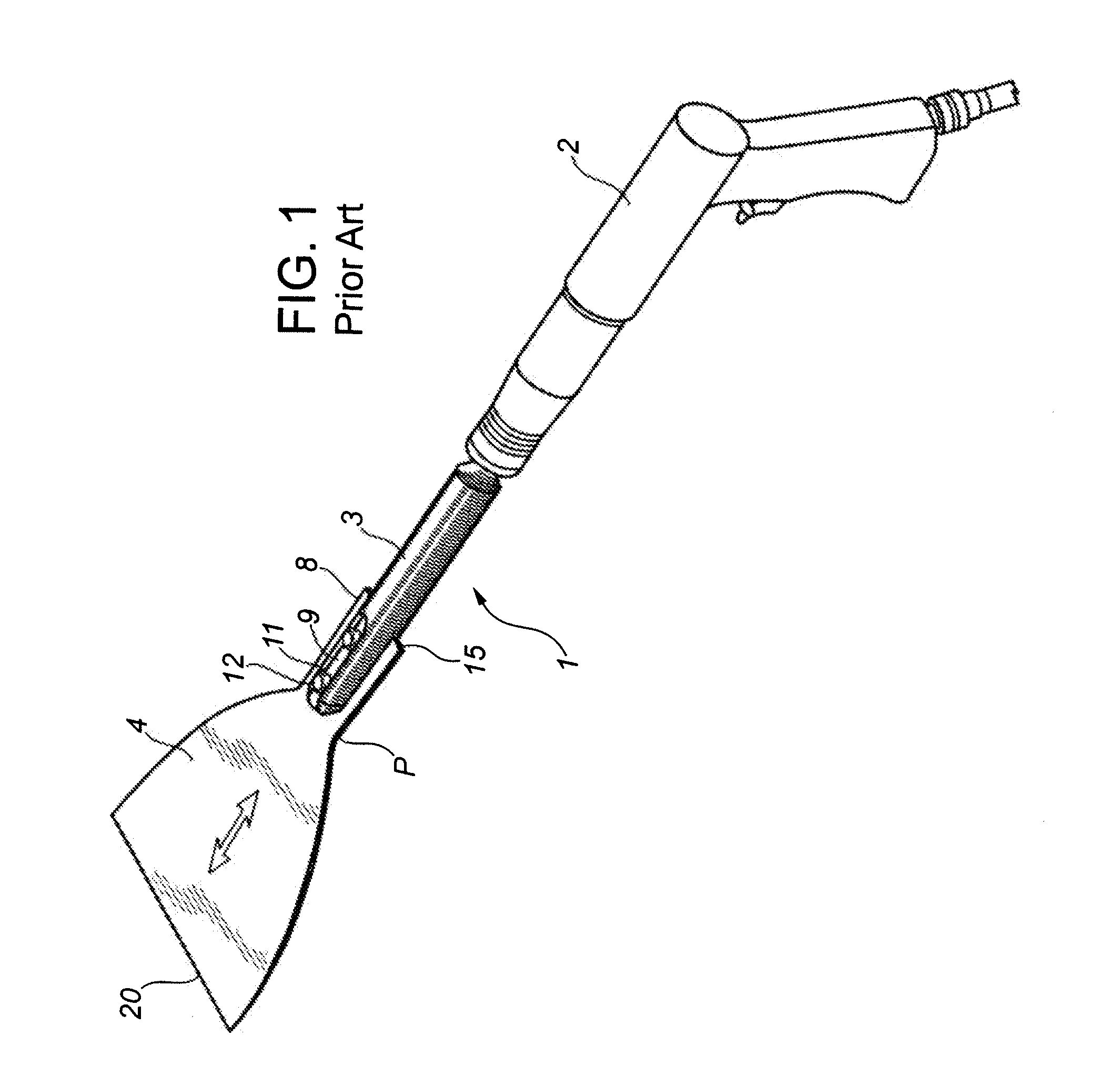
[0060] The windshield removal assembly 1 comprises a reciprocating power tool, such as an air gun 2, shaft 3 and blade 4. FIG. 1 shows the inventor's prior art version of the windshield removal assembly as described in U.S. Pat. No. 6,862,968 and U.S. Published Application No. 2005 / 0126359, wherein the power tool is an air gun 2, the shaft 3 reciprocates in a back and forth movement along the longitudinal axis of the shaft 3. The blade 4 is shown with its bell-shaped configuration. The stress point mentioned above, at the joining of the side edges to the shank, is shown at P.

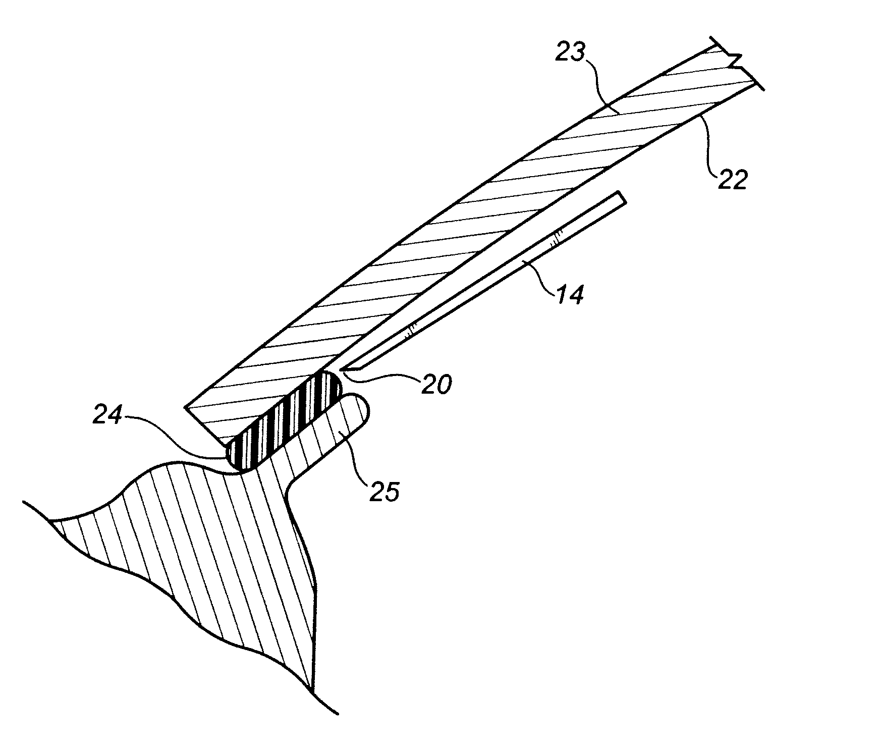
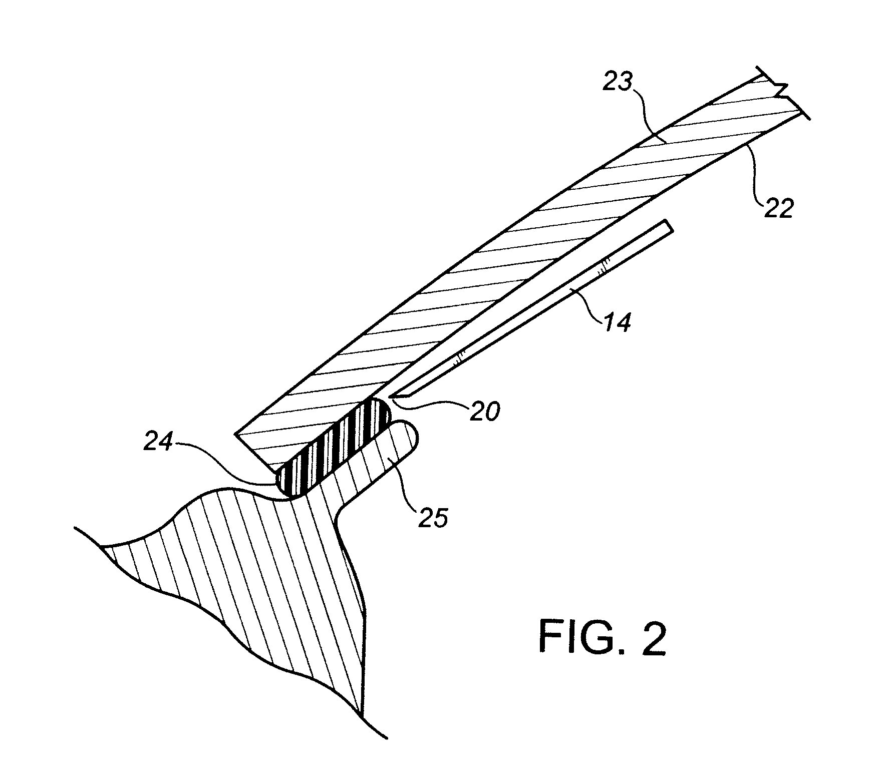
[0061] The present invention is shown in FIGS. 2-7, with like parts, compared to the prior art device of FIG. 1, being labeled with the same numerals.

[0062]FIG. 2 is schematic in nature, and is of assistance in describing the operation of assembly of the present invention. When assembled and operated, the blade 14 preferably reciprocates with a throw or travel of about ½ inch. The blade 14 is pressed against t...


PUM

PropertyMeasurementUnit
angleaaaaaaaaaa
angleaaaaaaaaaa
angleaaaaaaaaaa

Abstract

A windshield removal assembly, method and blade for same, with the thin metal blade having a unique delta-shape. The blade connects at its narrowed shank portion to the shaft of a reciprocating power tool. The blade has front and rear ends, the front end being substantially straight and wider than the blade rear end. The top edge of the blade forms a non-sharpened top edge on the front end and arc portions, while the bottom edge of the blade forms a sharpened bottom cutting edge which extends across the front end of the blade and along at least half of the arc portions. The blade has sufficient rigidity to cut the urethane bed when reciprocated, and sufficient lateral flexibility to conform to the curved surface of the windshield when pressed thereagainst.

Description

FIELD OF THE INVENTION [0001] This invention relates to a windshield removal assembly for cutting the urethane bed around the windshield perimeter and separating the glass windshield from the vehicle. The invention also relates to a method of removing a windshield with the assembly, and to a blade for use in the assembly. BACKGROUND OF THE INVENTION [0002] In the process of securing a glass windshield to a new car or truck, the manufacturer first extrudes a bead or “bed” of urethane onto the “pinch weld” extending around the perimeter of the window opening. The urethane bed bonds to the pinch weld surface. The glass windshield then is seated on the bed and bonds to it, forming a liquid-tight seal. The urethane bed is hard and tough and not easily penetrated. It commonly has a thickness of about ¼ inch and width of about ⅓-¾ inches, widening to about 3½-4″ or more at the corners. [0003] If the windshield is to be replaced, an installer severs the bed along its length, just beneath th...

Claims


Application Information

Patent Timeline
Patent Type & Authority Applications(United States)
IPC IPC(8): B26B7/00
CPCB26B7/00Y10T83/04Y10T83/0605
Inventor OGSTON, ALFRED JOHN
Owner CRYSTAL GLASS CANADA
Why Eureka
Try Eureka