Supercharge Your Innovation With Domain-Expert AI Agents!

Apparatus and method for forming optical element

a technology of optical elements and apparatuses, which is applied in the direction of manufacturing tools, instruments, food shaping, etc., can solve the problems of reducing design flexibility and complicated lens barrel design, and achieve the effects of reducing the risk of breakage, improving strength, and reducing the number of changeovers

Inactive Publication Date: 2007-11-01
SONY CORP
View PDF1 Cites 8 Cited by
  • Summary
  • Abstract
  • Description
  • Claims
  • Application Information

AI Technical Summary

Benefits of technology

[0011] (ii) In a case of installation the lens 101 to a lens barrel, the lens 101 having the burr 107 that occurs on an installation base surface where the lens 101 is installed to a barrel of a camera or the like, the lens 101 is so inclined inside a lens barrel 108 as to bring about deviation of an optical axis 109 as shown in FIG. 33, thereby requiring a deburring operation. As a method for preventing the deviation of the optical axis 109 without removing the burr 107, a clearance 110 for accommodating the burr 107 therein may be produced inside the lens barrel 108 as shown in FIG. 34. However, this complicates the design of the lens barrel 108 and degrades flexibility in design.
[0013] In view of the above, it is desirable to provide an apparatus and method for forming the optical element such as the lens, in which the deficit or crack (which is the biggest drawback that the forming mold made of glass or the like possesses) is difficult to adversely affect the product even if the deficit or crack occurs.
[0014] Additionally, it is desirable to provide an apparatus and method for forming the optical element such as the lens, in which the deburring operation after a forming operation may be not necessary.
[0017] In the apparatus for forming the optical element, according to the embodiment of the present invention, the mold member interposed between the facing surfaces of the pair of the forming molds is arranged to cover an outer peripheral portion that each of the forming molds has on its facing surface. Therefore, even if a fine damage such as a chip exists on the outer peripheral portion of the facing surface, the formed optical element can be prevented from a burr to be brought by the damage. Further, even if there is a crack on the outermost peripheral portion of the facing surface of the forming mold, the molten resin is prevented from flowing into the crack. This protects the forming mold from a situation where a part of the forming mold is peeled off in the vicinity of the crack when the resin hardens and shrinks.
[0018] The method for forming the optical element according to the embodiment of the present invention is a simple method, in which the optical element is formed upon interposing the mold member between the outer peripheral portions of the facing surfaces of the pair of the forming molds. In this method it is allowed to form the optical element while protecting the facing surfaces of the pair of the forming molds at its outermost peripheral portion by the mold member. It is further possible to form such an optical element as to be free from the burr and the like, even if there is a deficit or crack on the outermost peripheral portion of the facing surface of each of the pair of the forming molds.

Problems solved by technology

As has been discussed above it is necessary to employ a forming mold made of a transparent glass through which ultraviolet light can be transmitted in the apparatus and method for forming the optical element made of the ultraviolet hardening resin, which raises problems as will be discussed hereinafter.
However, this complicates the design of the lens barrel 108 and degrades flexibility in design.

Method used


Image

  • Apparatus and method for forming optical element
  • Apparatus and method for forming optical element
  • Apparatus and method for forming optical element

Examples


Embodiment Construction

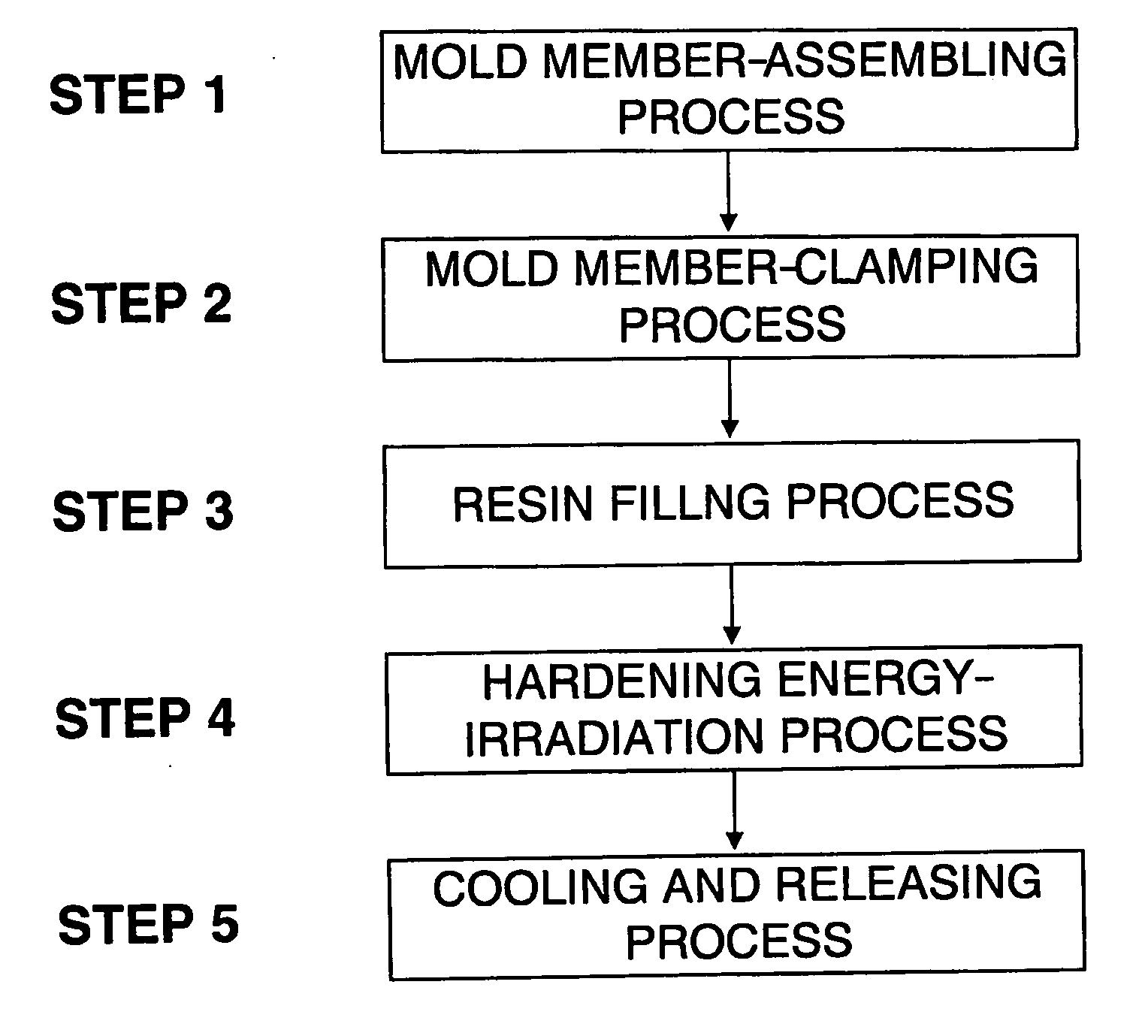
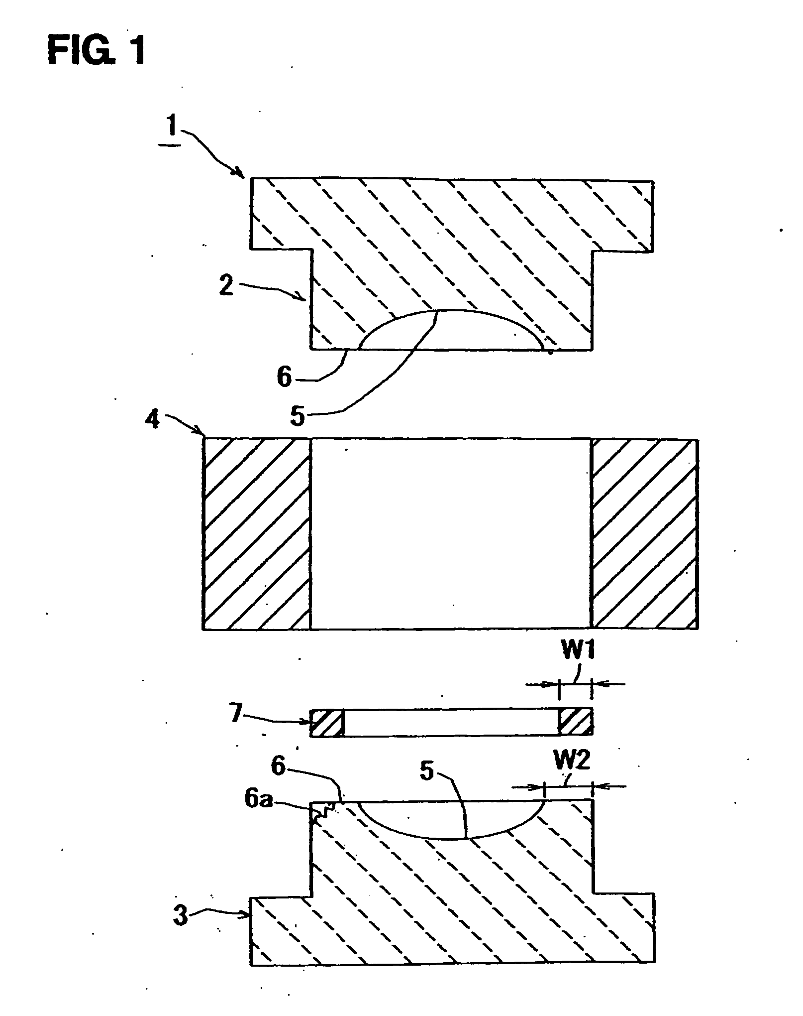
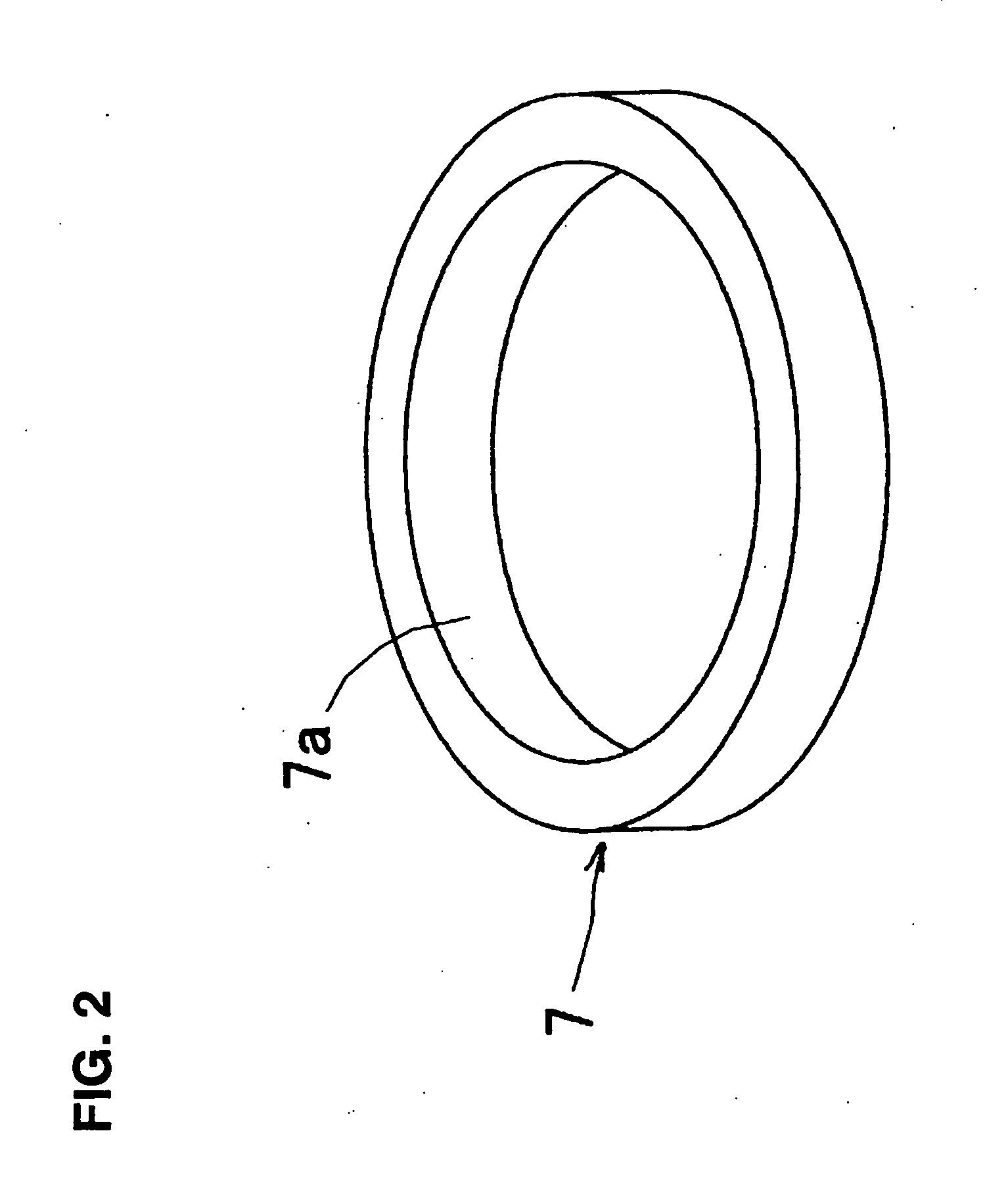
[0058] Referring now to the accompanying drawings, an embodiment of an apparatus and method for forming an optical element, according to the present invention will be discussed. FIG. 1 is a cross-sectional view of an embodiment of an apparatus 1 for forming an optical element, according to the present invention. The apparatus 1 will be hereinafter abbreviated as merely “a forming apparatus 1”. FIG. 2 is a perspective view of a mold member. FIG. 3 is a flow chart of a forming method. FIGS. 4 to 8 are schematic cross-sectional views showing each step taken for forming the optical element in the use of the forming apparatus 1.

[0059] As shown in FIG. 1, the forming apparatus 1 includes a pair of forming molds, i.e. first (or upper) and second (or lower) forming molds 2 and 3, and a sleeve 4 for carrying out a centering of the first and second forming molds 2 and 3. The first and second forming molds 2 and 3 are made of glass through which ultraviolet light can be transmitted. The glass...


PUM

PropertyMeasurementUnit
Energyaaaaaaaaaa
Compatibilityaaaaaaaaaa

Abstract

An apparatus for forming an optical element. The apparatus includes a pair of forming molds each of which has a facing surface facing to each other. At least one of the pair of the forming molds is made to allow a hardening energy to pass through itself. A frame-like mold member is provided to be interposed between the facing surfaces of the pair of the forming molds to cover an outer peripheral portion that each of the forming molds has on its facing surface, thereby defining a cavity. In the thus arranged apparatus, an energy hardening resin is filled into the cavity and then hardened by being subjected to the hardening energy passing through the at least one of the pair of the forming molds.

Description

CROSS REFERENCES TO RELATED APPLICATIONS [0001] The present invention contains subject matter related to Japanese Patent Application JP 2006-124771 filed in the Japanese Patent Office on Apr. 28, 2006, the entire contents of which being incorporated herein by reference. BACKGROUND OF THE INVENTION [0002] This invention relates to an apparatus and method for forming an optical element made of an ultraviolet hardening resin. [0003] Optical elements, such as lenses used in optical devices including cameras and the like, are commonly made of glass or plastic. The optical elements made of plastic are light in weight, and are excellent in impact resistance and manufacturing cost as compared with those made of glass. Hence, the optical elements made of plastic are widely applied to numerous kinds of optical devices. [0004] The optical elements made of plastic are known to be formed by using a thermoplastic resin, a thermosetting resin, or the ultraviolet hardening resin. [0005] The optical...

Claims


Application Information

Patent Timeline
IPC IPC(8): B29D11/00
CPCB29C35/0888B29C2035/0827B29D11/00413B29L2011/0016B29K2105/0002B29K2909/08B29D11/00528Y10S425/808
Inventor TSUJI, TAKUMI
Owner SONY CORP
Features
  • R&D
  • Intellectual Property
  • Life Sciences
  • Materials
  • Tech Scout
  • Unparalleled Data Quality
  • Higher Quality Content
  • 60% Fewer Hallucinations
Learn More