
Read/write system for a hard drive

a hard drive and read/write technology, applied in the field of hard drives of computers, can solve the problems of increasing susceptibility, reducing the overall dimensional consistency between the components, and requiring a large number of separate parts, and achieve the effect of rapid data movemen

Inactive Publication Date: 2007-11-01
HALL KENNETH D
View PDF14 Cites 3 Cited by
  • Summary
  • Abstract
  • Description
  • Claims
  • Application Information

AI Technical Summary

Benefits of technology

[0021] It is a main object of the present invention to provide a means to improve the speed of a hard drive without the drawbacks discussed above.
[0022] It is another object of the present invention to provide a means for improving hard drive performance in a manner that does not require operations by a sophisticated consumer. SUMMARY OF THE INVENTION
[0024] Using the system embodying the present invention will permit rapid data movement to and / or from the hard disc without the problems encountered with the prior art. Multiple tracks can be read or written simultaneously.

Problems solved by technology

One drawback of conventional spindle motors is that a number of separate parts are required to fix motor components to one another.
This can lead to stack up tolerances which reduce the overall dimensional consistency between the components.
This results in more susceptibility to problems induced by differing coefficients of thermal expansion than other metals used in existing spindle motors, making it difficult to maintain dimensional consistency over the operating temperature that the drive sees between the hydrodynamic bearings and other metal parts of the motor.
Hydrodynamic bearings have less stiffness than conventional ball bearings so they are more susceptible to imprecise rotation when exposed to vibrations or shock.
Presently this spacing between portions of information is limited due to vibrations occurring during the operation of the motor.
These vibrations can be caused when the stator windings are energized, which results in vibrations of a particular frequency.
These vibrations also occur from harmonic oscillations in the hub and discs during rotation, caused primarily by non-uniform size media discs.
Increased motor temperature affects the electrical efficiency of the motor and bearing life.
As temperature increases, resistive loses in wire increase, thereby reducing total motor power.
Furthermore, it can be predicted that the failure rate of an electrical device is exponentially related to its operating temperature.
Also, as bearings get hot they expand, and the bearing cages get stressed and may deflect, causing non-uniform rotation and the resultant of further heat increase, non-uniform rotation requiring greater spacing in data tracks, and reduced bearing life.
One drawback with existing motor designs is their limited effective dissipation of the heat, and difficulty in incorporating heat sinks to aid in heat dissipation.
In addition to such outgassed materials, airborne particulate matter in a drive may lead to head damage.
Also, airborne particulates in the disc drive could interfere with signal transfer between the read / write head and the media.
Heads used in disc drives are susceptible to damage from electrical shorts passing through a small air gap between the media and the head surface.
A drawback to this design is the requirement of an extra component.
Furthermore, due to the consuming public's awareness of various performance specifications, many hard drive vendors have opted for faster external interface timing specifications.
However for various architectural reasons, having faster external interface timing does not necessarily result in overall faster throughput.
A faster external interface could result in decreased throughput if the hard drive is unable to sustain the reading of data from sequential sectors without experiencing missed revolutions.
By having a very aggressive external interface timing the proper balance of access between the external interface, the internal read / write heads, and the internal data buffer might not be achieved, causing the internal read / write heads being denied access to the single ported internal data buffer at the beginning of a sector, resulting in missed disk revolutions.
Even for these sophisticated users, very little help is available for them to ascertain what the appropriate Transfer Block Size should be.

Method used


Image

  • Read/write system for a hard drive
  • Read/write system for a hard drive
  • Read/write system for a hard drive

Examples


Embodiment Construction

[0031] Other objects, features and advantages of the invention will become apparent from a consideration of the following detailed description and the accompanying drawings.

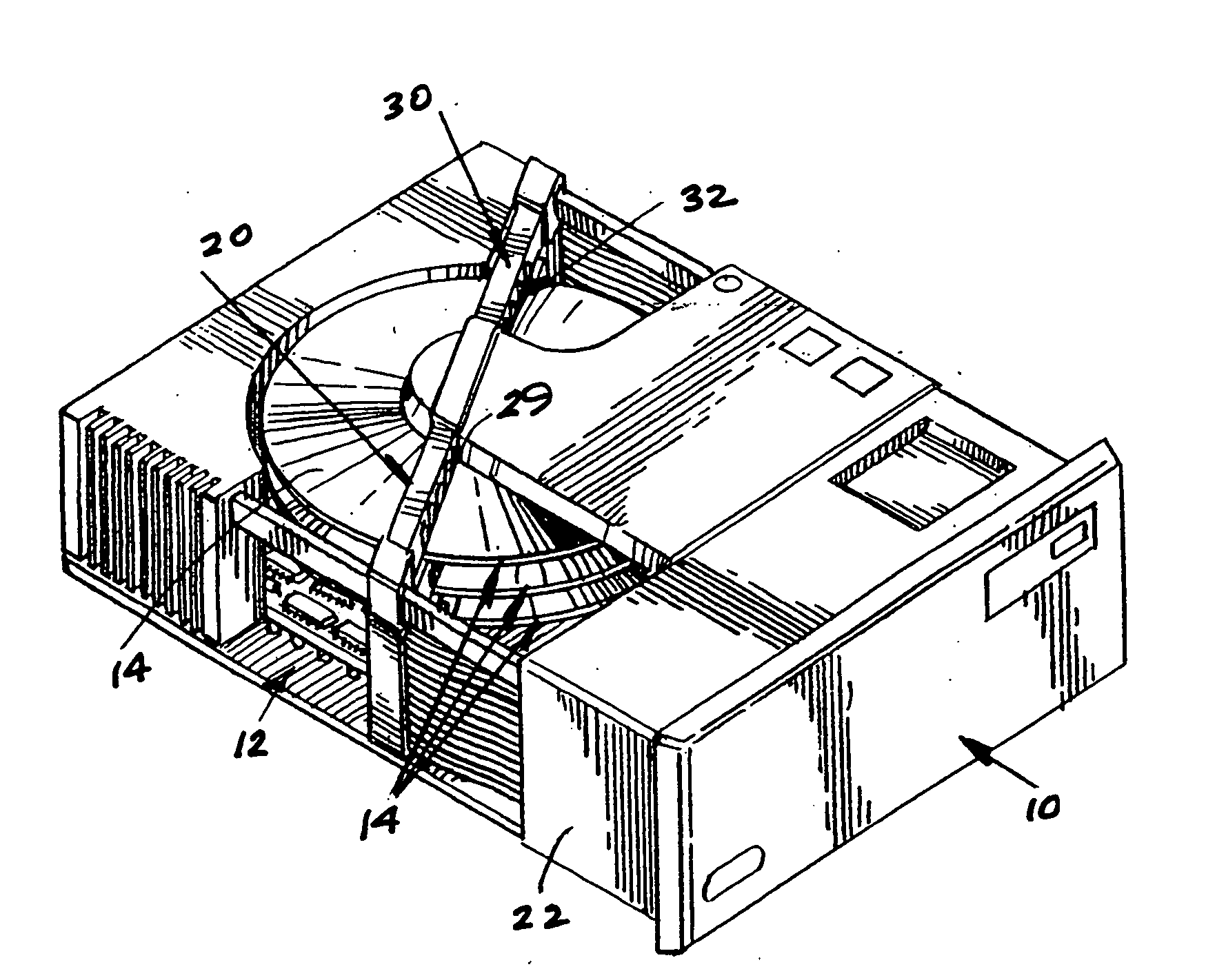
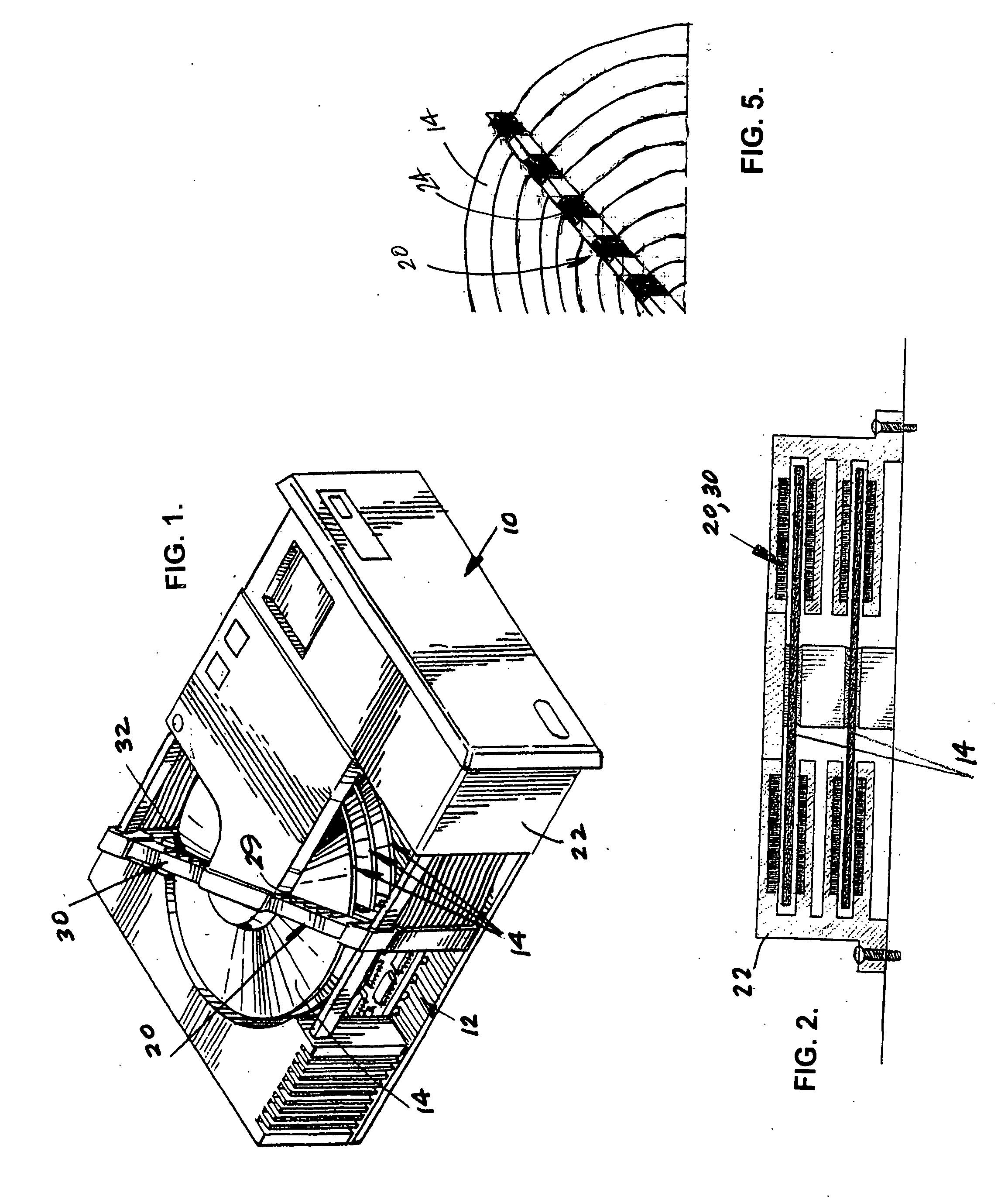
[0032] Referring to the Figures, it can be understood that the present invention is embodied in a read / write system 10 for a hard drive 12 which achieves the above-stated objectives.

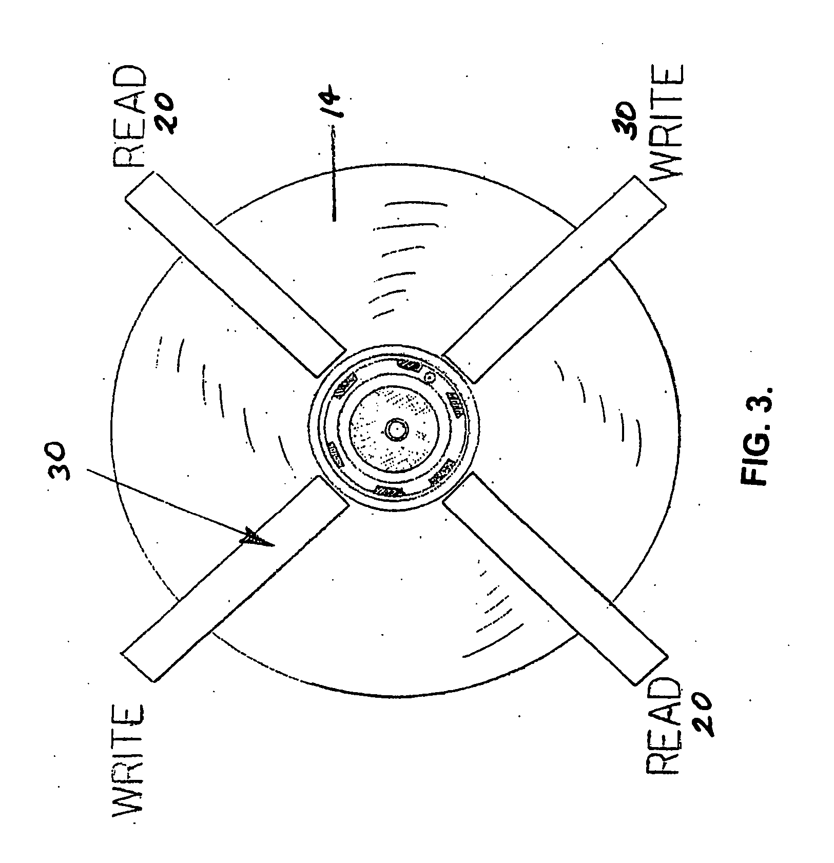
[0033] System 10 comprises a hard drive disc 14 which is rotated during use as will be understood by those skilled in the art.

[0034] System 10 further comprises a read head unit 20 which is fixed in place with respect to hard drive disc 14 whereby the hard drive disc 14 rotates with respect to the read head unit 20. The read head unit 20 can be fixedly mounted on a housing 22 or the like.

[0035] As can be understood from FIG. 5, read head unit 20 includes a plurality of data reading elements 24 located to read data from the hard drive disc 14 when necessary.

[0036] System 10 further includes a write head unit 30 which is fixed in p...


PUM

PropertyMeasurementUnit
magneticaaaaaaaaaa
speedaaaaaaaaaa
rotationaaaaaaaaaa

Abstract

A read head unit and a write head unit are fixed in place with respect to a rotating disc which rotates beneath the fixed head units. Each head unit includes a plurality of elements to read data from, or write data onto, the disc as appropriate.

Description

BACKGROUND OF THE INVENTION [0001] 1. Field of the Invention [0002] The present invention relates to the general art of computer hardware, and to the particular field of hard drives of computers. [0003] 2. Description of the Related Art [0004] Computers commonly use disc drives for memory storage purposes. Disc drives include a stack of one or more magnetic discs that rotate and are accessed using a head or read-write transducer. Typically, a high speed motor such as a spindle motor is used to rotate the discs. [0005] An example of a conventional spindle motor includes a base which is usually made from die cast aluminum, a stator, a shaft, bearings and a disc support member, also referred to as a hub. A magnet and flux return ring are attached to the disc support member. The stator is separated from the base using an insulator and attached to the base using an adhesive. Distinct structures are formed in the base and the disc support member to accommodate the bearings. One end of the...

Claims


Application Information

Patent Timeline
Patent Type & Authority Applications(United States)
IPC IPC(8): G11B5/55
CPCG11B5/49
Inventor HALL, KENNETH D.
Owner HALL KENNETH D
Learn More