LED backlight and liquid crystal display device using thereof

a liquid crystal display device and backlight technology, applied in the field of led backlights, can solve the problems of poor red color reproduction capability of backlights employing leds, difficult to mix light from these primary colors, and low color reproduction capability, and achieve the effects of improving the color reproduction capability of backlights, high color uniformity, and high intensity

Inactive Publication Date: 2007-11-01
PANASONIC LIQUID CRYSTAL DISPLAY CO LTD
View PDF7 Cites 29 Cited by
  • Summary
  • Abstract
  • Description
  • Claims
  • Application Information

AI Technical Summary

Benefits of technology

[0011]The present invention enables backlights to achieve high luminance and enhanced color reproduction capability by using high intensity white LEDs and single color LEDs (namely, red LEDs) in combination and fully mixing light from them. Particularly, the present invention can be advantageously applied to side backlights of small and medium size using a general light guide plate.
[0015]Thus, a sufficient amount of light is introduced from the white LEDs (serving as a light source) into the light guide plate. Further, light from the single color LEDs (red LEDs) is uniformly introduced from the light diffusing optical waveguide into the light guide plate. These allow the backlight to function as a surface light source emitting high intensity light having high color uniformity. Further, the above arrangement adds red wavelengths to the apparent white light from the white LEDs, which is deficient of such wavelengths, to improve the color reproduction capability of the backlight.
[0016]Thus, the present invention combines the advantages of a white LED backlight and a three primary color LED backlight. Since a white LED backlight uses white LEDs as its light source (instead of using three primary color LEDs and mixing light from them), it can provide light of high color uniformity, as compared to a three primary color LED backlight. Therefore, according to the present invention, apparent white light from the white LEDs, which is deficient of red wavelengths, is mixed with red light from single color LEDs (red LEDs) to improve the color reproduction capability of the backlight.
[0017]That is, in the white LED backlight of the present invention, the white LEDs emit high intensity light, which results in high luminance of the backlight. Further, the light diffusing optical waveguide functions to uniformly introduce light from the primary color LEDs (red LEDs) into the light guide plate, thereby enhancing the color reproduction capability of the backlight. In this way, the present invention combines the advantages of a white LED backlight and a three primary color LED backlight.
[0018]Thus, the backlight of the present invention has a reduced thickness, includes a reduced number of LEDs, and yet produces high intensity light having high color uniformity. The present invention also provides a TFT liquid crystal display device that can display a clear image by using this backlight.

Problems solved by technology

Conventional LED backlights employing white LEDs have an advantage over LED backlights employing three primary color LEDs (i.e., red, green, and blue LEDs) in terms of luminance uniformity and color uniformity, but have lower color reproduction capability.
Therefore, LED backlights employing while LEDs have poor red color reproduction capability.
However, it is difficult to mix light from these primary color LEDs so as to produce white light having high color uniformity.
Further, in the case of LED backlights using three primary color LEDs, these LEDs must be disposed in close proximity to mix light from them, which means that each LED is heated by heat from the adjacent LEDs, resulting in reduced luminous efficiency.
Further, the. apparent white light emitted by the white LEDs has no intensity peak at red wavelengths and hence does not include sufficient red color components, since it is produced by mixing blue wavelength light from a blue LED and yellow wavelength light emitted by a yellow fluorescent material when the material is excited by that blue wavelength light, as described above.

Method used


Image

  • LED backlight and liquid crystal display device using thereof
  • LED backlight and liquid crystal display device using thereof
  • LED backlight and liquid crystal display device using thereof

Examples


first embodiment

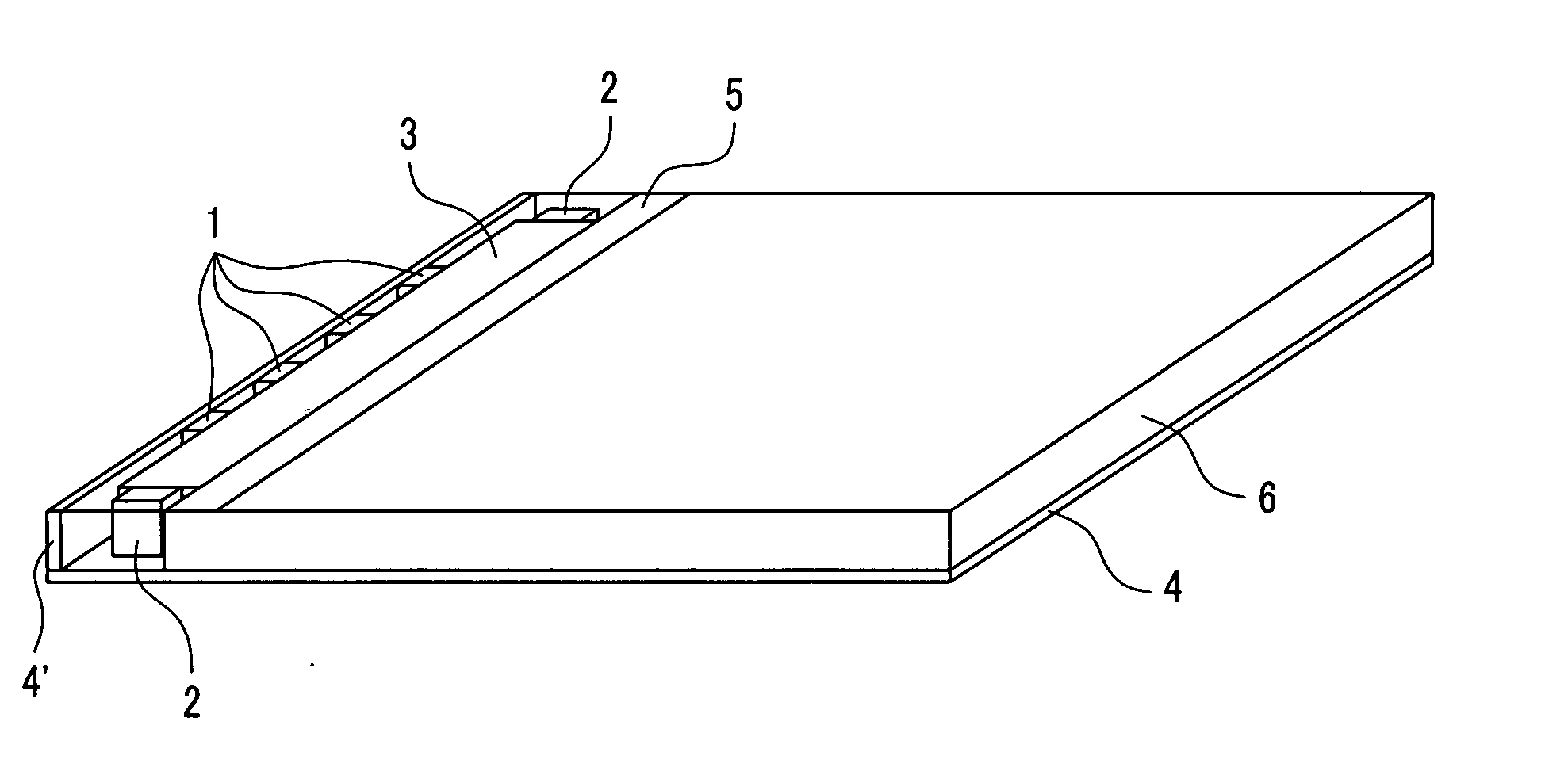
[0029]FIG. 1 is a diagram showing the configuration of an LED backlight according to a first embodiment of the present invention. Referring to FIG. 1, white light from a plurality of white LEDs 1 passes through a light diffusing optical waveguide 3 to enter a light guide plate 6 through a side thereof. The white light that has entered the light guide plate 6 is repeatedly reflected by a reflector plate (or LED mounting substrate) 4 such that the light exits through the entire upper surface of the light guide plate 6. A liquid crystal panel (not shown) is disposed on the upper side of the light guide plate 6, and the white light emitted from the entire upper surface of the light guide plate 6 is controlled by the liquid crystal elements arranged in a matrix configuration within the liquid crystal panel to display an image.

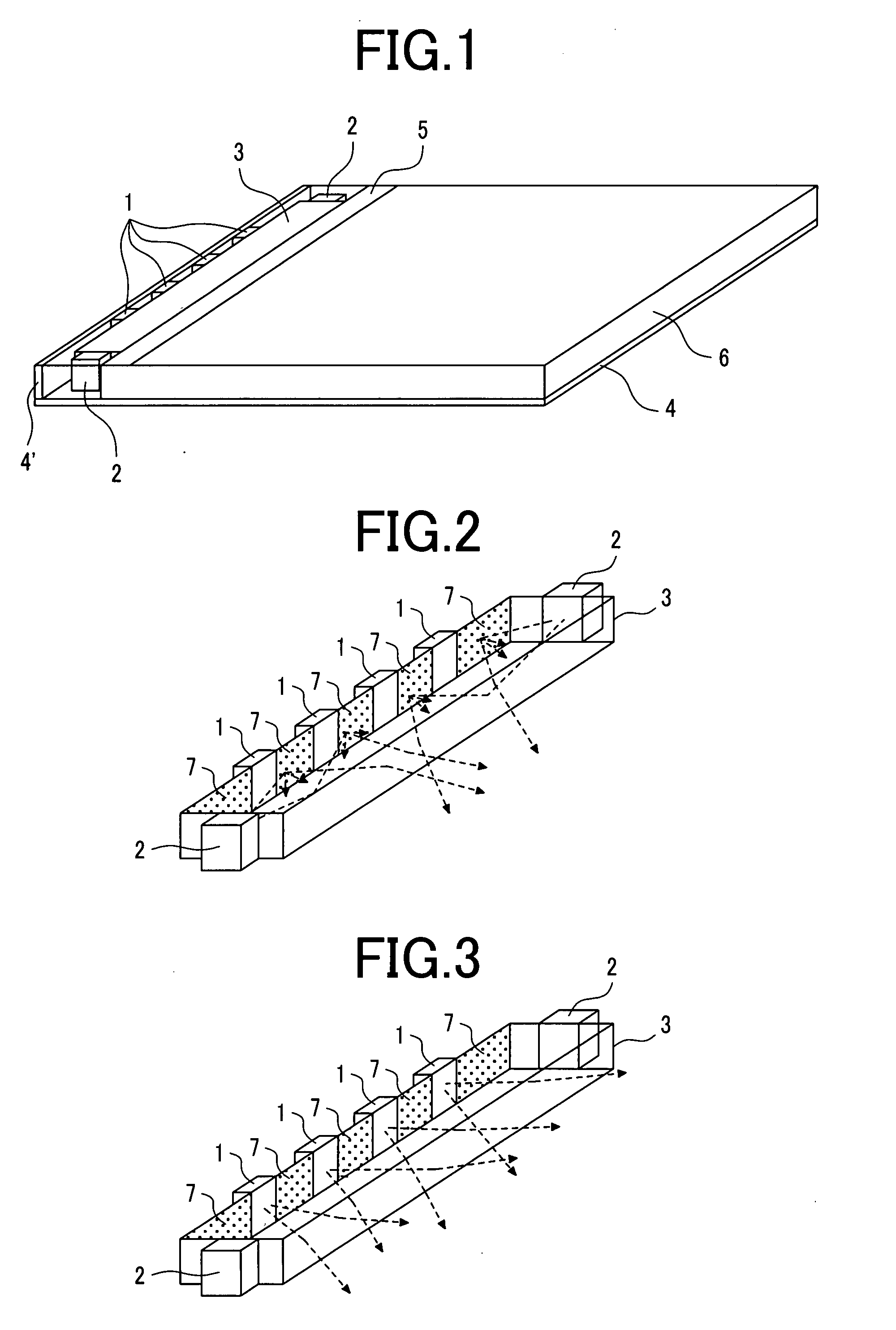
[0030]At the same time, single color light from single color LEDs (red LEDs) 2 disposed on both sides of the light diffusing optical waveguide 3 is diffused within ...

second embodiment

[0040]A light diffusing optical waveguide 3 in accordance with a second embodiment of the present invention will be described with reference to FIGS. 5 to 9.

[0041]FIGS. 5A to 5D illustrate grooves formed in a surface of the light diffusing optical waveguide 3, and their effect (these grooves constituting light diffusing portions 7). Specifically, FIG. 5A is a detailed diagram of the light diffusing optical waveguide 3; FIG. 5B shows the groove pattern; FIG. 5C is an enlarged view of the groove pattern; and FIG. 5D is a schematic diagram showing the paths of light from a single color LED 2.

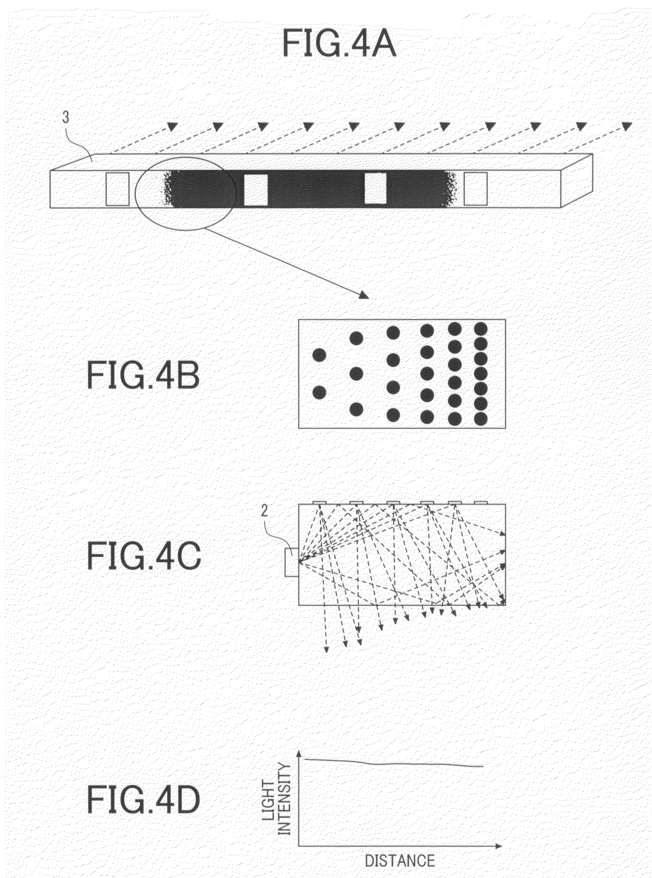
[0042]Referring to FIG. 5A, the light diffusing optical waveguide 3 of the present embodiment has grooves formed on its light exit side, i.e., on the light guide plate side (whereas the light diffusing optical waveguide 3 of the first embodiment shown in FIG. 4 has white dots printed on its light receiving side). This arrangement allows light from the white LEDs 1 and the single color LEDs 2 to be ...


PUM


Abstract

An object of the present invention is to improve the color reproduction capability of a liquid crystal display backlight using white LEDs.A backlight of the present invention includes: a light guide plate 6; a light diffusing optical waveguide 3 disposed adjacent the light guide plate 6; a plurality of white LEDs 1 disposed on the light diffusing optical waveguide 3; and single color LEDs (red LEDs) 2 disposed on respective opposite sides of the light diffusing optical waveguide 3; wherein light from the white LEDs 1 passes through the light diffusing optical waveguide 3 and enters the light guide plate 6 through a side thereof, whereas light from the single color LEDs 2 is diffused by the light diffusing optical waveguide 3 before entering the light guide plate 6 through the same side thereof. Thus, the light diffusing optical waveguide 3 mixes light from the white LEDs 1 and single color LEDs 2, resulting in improved color reproduction capability of the backlight.

Description

CLAIM OF PRIORITY[0001]The present application claims priority from Japanese Application JP 2006-124814 filed on Apr. 28, 2006, the content of which is hereby incorporated by reference into this application.BACKGROUND OF THE INVENTION [0002]1. Field of the Invention[0003]The present invention relates to an LED backlight, and more particularly to a white LED backlight having improved color reproduction capability, or color rendering capability, and to a liquid crystal display device using it.[0004]2. Description of the Related Art[0005]Japanese Patent Laid-Open No. 2004-158452 discloses a backlight unit in which a refracting member is provided between white LEDs and a light guide plate to refract and redirect light from the white LEDs to emerge in the direction of the light guide plate. Further, Japanese Patent Laid-Open No. 2005-56842 discloses a backlight assembly that uses both white LEDs and single-color LEDs (red LEDs) to achieve enhanced color reproduction capability.[0006]Conv...

Claims


Application Information

Patent Timeline
Patent Type & Authority Applications(United States)
IPC IPC(8): F21V7/04
CPCG02B6/0028G02B6/0068G02B6/0061G02B6/0038
Inventor WATANABE, SABURO
Owner PANASONIC LIQUID CRYSTAL DISPLAY CO LTD
Why Eureka
Try Eureka