Systems and methods for performing automated conversion of representations of synchronous circuit designs to and from representations of asynchronous circuit designs

a technology of synchronous circuit design and asynchronous circuit design, applied in the field of electronic circuit design, can solve the problems of time-consuming, inconvenient, and inability to meet the needs of designers, and achieve the effect of facilitating feedback to synchronous design tools

Active Publication Date: 2007-11-01
ACHRONIX SEMICON CORP
View PDF14 Cites 78 Cited by
  • Summary
  • Abstract
  • Description
  • Claims
  • Application Information

AI Technical Summary

Benefits of technology

[0014]By providing an optimized, automated, non-Interactive conversion of representations of synchronous circuit designs to and from representations of asynchronous circuit designs, the invention allows traditional electronic design automation (EDA) tools to process and manipulate asynchronous designs while allowing synchronous designs to be implemented using asynchronous hardware solutions. The invention also facilitates feedback to synchronous design tools in synchronous representation for optimization and iteration of the design process by engineers. The inventive method can also preserve the illusion of synchrony at the primary inputs and outputs of the circuit being converted.

Problems solved by technology

Approach (1) above is time intensive and involves re-implementing an entire design for execution in an asynchronous architecture.
This is an approach that is not generally acceptable to designers.
It is costly in terms of time and requires that designers learn a completely new way to represent circuit designs ; in an asynchronous format.
Automated conversion of synchronous circuit designs to asynchronous representations have been discussed, but to the best knowledge of the inventors, has never been implemented in an effective, commercially viable solution.
No existing art addresses the problem of converting synchronous circuit designs in the presence of multiple clock domains, latches and flip-flops (positive and negative triggered), and clock gating.
Also, there is no prior work known to the inventors whereby to convert a synchronous system into an asynchronous design while preserving the illusion of synchrony on the primary inputs and outputs.

Method used


Image

  • Systems and methods for performing automated conversion of representations of synchronous circuit designs to and from representations of asynchronous circuit designs
  • Systems and methods for performing automated conversion of representations of synchronous circuit designs to and from representations of asynchronous circuit designs
  • Systems and methods for performing automated conversion of representations of synchronous circuit designs to and from representations of asynchronous circuit designs

Examples


Embodiment Construction

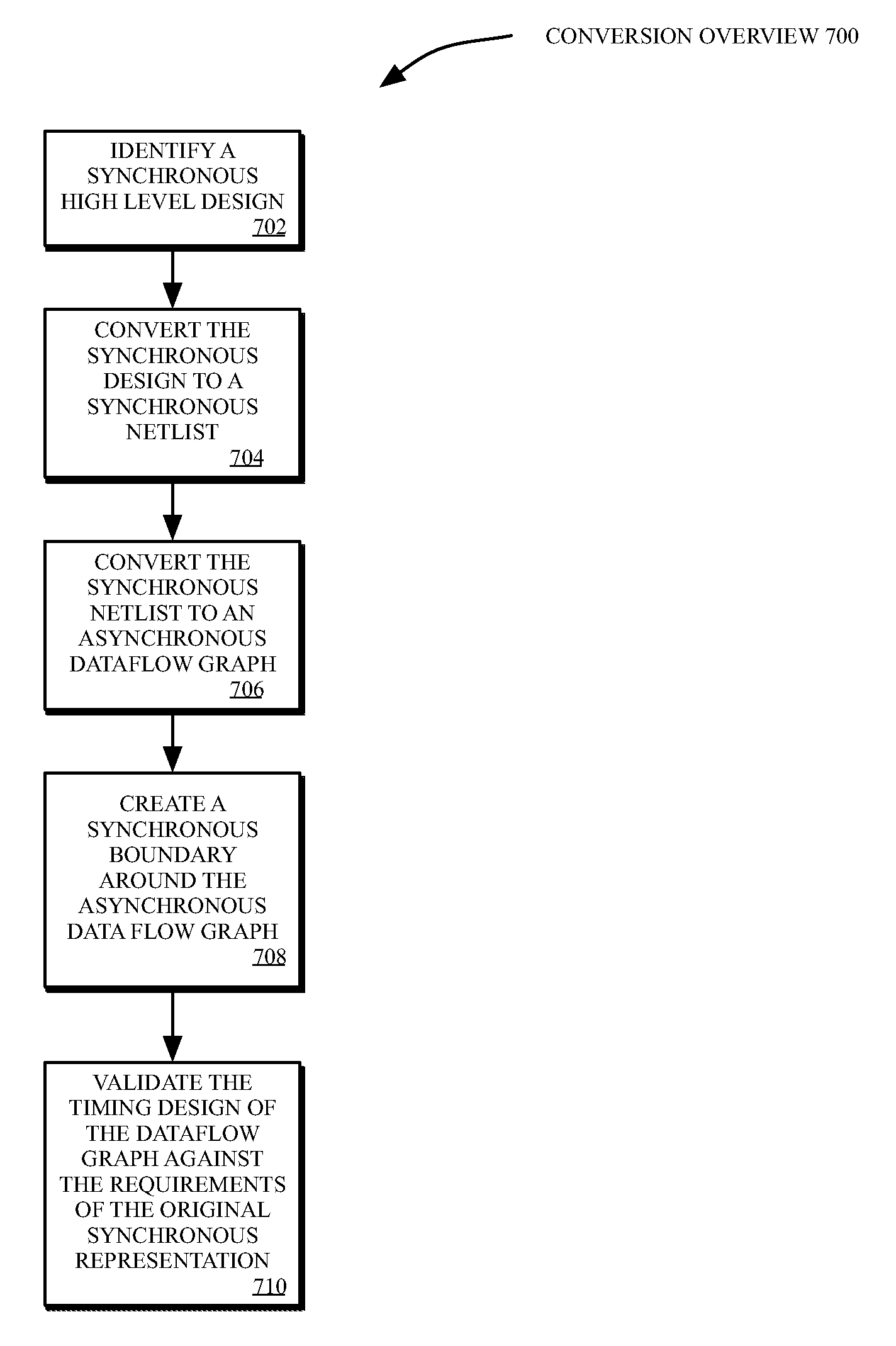
[0026]The invention is a method for converting a synchronous design into an asynchronous one with equivalent functionality. The method is general in that it can convert circuits with an arbitrary number of clock domains as long as the frequency of each clock domain is known beforehand. The method can also handle common features such as clock gating, combinations of positive edge-triggered and negative edge-triggered flip-flops, as well as latches. The method also includes provisions for making any asynchronous signal behave completely synchronously. This can be applied to the primary inputs and outputs of the circuit to hide the asynchronous nature of its core implementation, or to any intermediate signal to enable synchronous scan-testing or synchronous debugging of a design.

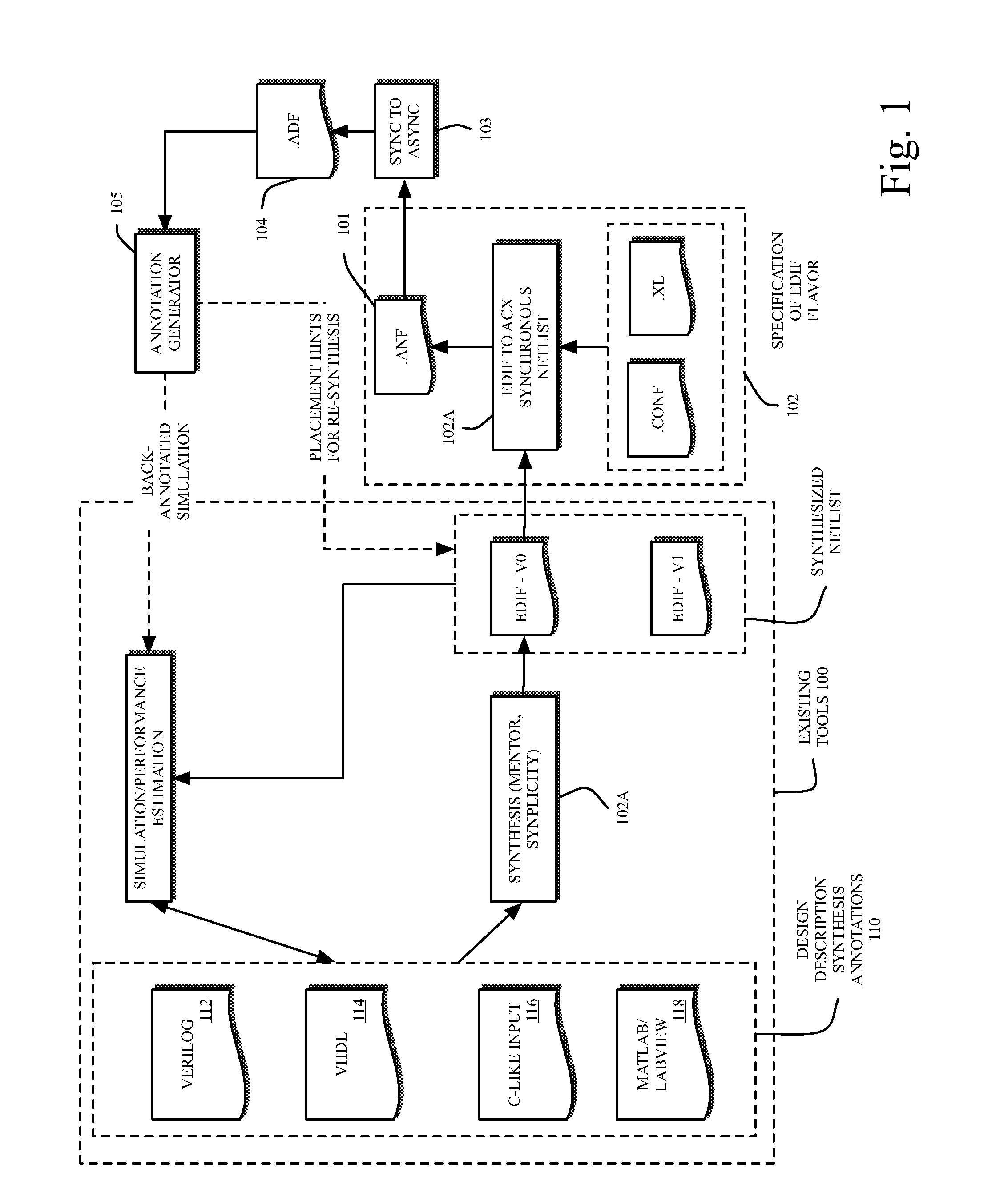
[0027]The input to the algorithm is a description of a synchronous netlist with additional auxiliary information that is normally required for synthesis. This information includes the set of clocks and their fr...


PUM


Abstract

Methods and systems automate an approach to provide a way to convert a circuit design from a synchronous representation to an asynchronous representation without any designer or user interaction or redesign of the synchronous circuit. An optimized, automated, non-Interactive conversion of representations of synchronous circuit designs to and from representations of asynchronous circuit designs, facilitating traditional electronic design automation (EDA) tools to process and manipulate asynchronous designs while allowing synchronous designs to be implemented using asynchronous hardware solutions. The invention also facilitates feedback to synchronous design tools in synchronous representation for optimization and iteration of the design process by engineers, eliminating the need for engineers to be aware of the underlying asynchronous architecture of the underlying hardware implementation.

Description

CROSS-REFERENCE TO RELATED APPLICATIONS [0001]This application claims the benefit of U.S. patent application Ser. No. 60 / 796,126 filed Apr. 27, 2006.FIELD OF THE INVENTION [0002]The present invention relates generally to electronic circuit design and more particularly to methods and systems for converting between synchronous and asynchronous circuit designs.BACKGROUND OF THE INVENTION [0003]Traditional synchronous circuit designs are represented using a variety of hardware description languages, higher level description languages, netlists, and schematics. All of these synchronous representations define the functionality of the circuits in the presence of a clock signal or with a master timing signal used to synchronize operations. To utilize an asynchronous architecture to implement the same synchronous circuit, the synchronous representation must be translated into an asynchronous representation. To accomplish this goal, there have been generally known to be two fundamental approa...

Claims


Application Information

Patent Timeline
Patent Type & Authority Applications(United States)
IPC IPC(8): G06F17/50
CPCG06F17/5045G06F30/30
Inventor MANOHAR, RAJIT
Owner ACHRONIX SEMICON CORP
Why Eureka
Try Eureka