Method and Device for Measuring

Inactive Publication Date: 2007-11-08
UNIV GENT
View PDF12 Cites 20 Cited by
  • Summary
  • Abstract
  • Description
  • Claims
  • Application Information

AI Technical Summary

Benefits of technology

[0030] It is an advantage of the present invention that it can be used for measuring speeds of objects in motion and/or for measuring speeds of fluids and/or for determining the flow direction of a fluid.
[0031] It is furthermore an advantage of the embodiments of the present invention that it is suitable for measuring in ‘dirty’ media e.g. fluids containing soot, dust, impurities, etc.
[0032] It is also an advantage of the embodiments of the present invention that they have a differential pressure gain of more than 30%, preferably more than 40%, more preferably more than 44%, even more preferably more than 48%, still more preferably more than 50% with respect to the dynamic pressure, as measured by a Pitot-static tube over broad ranges.
[0033] It is furthermore an

Problems solved by technology

The main disadvantages however are that it generates a high-pressure loss, that it is nonlinear and that it is sensitive to installation effects and mechanical wear.
However, the initial installation costs are much higher, a considerable length of the pipe for probing is required and it generates a differential pressure that is lower for a same area ratio than for the orifice.
Although Pitot tubes can be designed such that they are independent from the Mach number (M200), as described by Van den Braembussche in Measurement Techniques in Fluid Dynamics—An Introduction (1994), and that they have a wide range of insensitivity to angular variations, their main disadvantage is that the pressure ports easily can

Method used


Image

  • Method and Device for Measuring
  • Method and Device for Measuring
  • Method and Device for Measuring

Examples


first embodiment

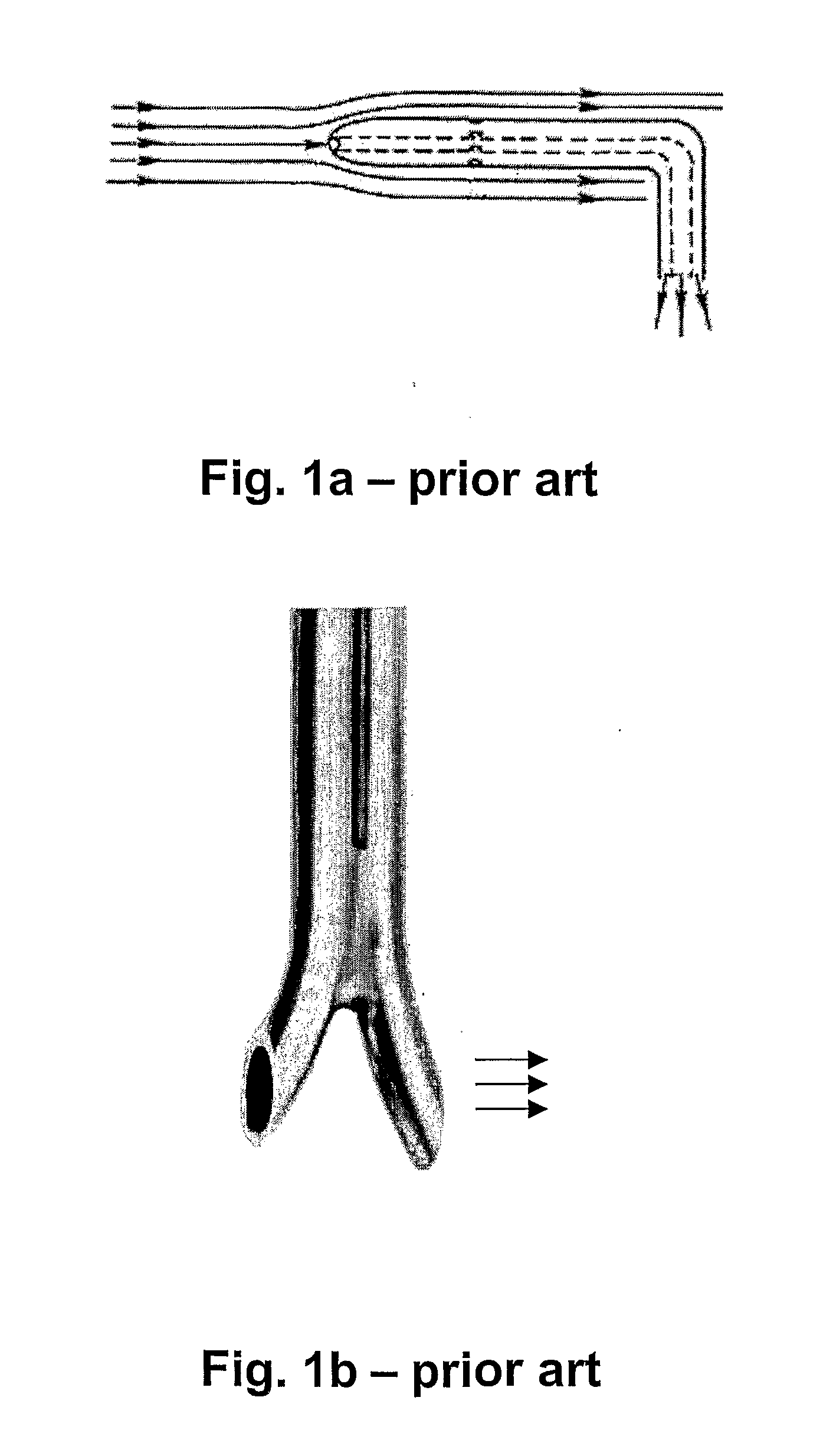
[0067] In a first embodiment, the invention relates to a pressure probe allowing to combine correct pressure measurement with flow angle independency, Reynolds independency and, if two measurements are carried out, with a high differential pressure gain. Several examples of such pressure probes are shown in FIG. 4 to FIG. 8.

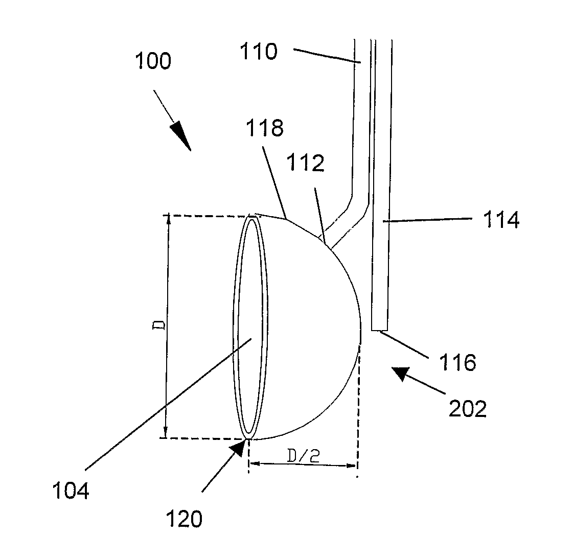
[0068] The pressure probe 100 comprises a bulbous part 102 wherein at the front side, facing the flow, either a planar surface or a recess 104 is provided. The recess 104 may be concave. If a recess 104 is present, it has a front opening 106 and a back portion also referred to as inner surface 108. In the embodiment illustrated, the device furthermore comprises two pressure sensing lines, a first one being a high pressure sensing line 110, which has a sensing port 112 in the recess 104 and a second pressure sensing line, being a low pressure sensing line 114 at the back or the side portion of the bulbous part 102, having a sensing port 116 in a region of lower pr...

second embodiment

[0075] In a second embodiment, the present invention relates to a pressure probe having a front side, adapted to face upstream, and a spherical shaped bulbous part 202. Examples of these probes are shown in FIG. 9, FIG. 10 and FIG. 11. The spherical shaped bulbous part 202 has an outer surface 118 that either can be a sphere or part thereof. Typically the outer surface 118 can be half a sphere, the device then being referred to as a hemisphere, can be a partial sphere being larger than half a sphere, the device then being referred to as a positively extended hemisphere, or can be a partial sphere being less than half a sphere, the device then being referred to as a negatively, cut hemisphere The extended hemisphere and the cut hemisphere thus can be seen as a hemispherical shape whereby at the front side respectively a part is added or a part is cut off. The latter is illustrated in FIG. 11, hereby a part with width x is removed from the hemisphere to obtain a cut hemisphere. The an...


PUM


Abstract

The invention relates to a pressure probe for characterizing the pressure and/or differential pressure in a fluid, and all derivatives, like for instance, flow rate. The device comprises a front side adapted for facing an upstream direction of the fluid flow, a bulbous part adapted for creating a region of low pressure, also called wake, and a flow detachment means. The front side allows creation of a region of high pressure. It has a planar shape or the shape of a recess. The device thus allows to be substantially flow angle independent, to be Reynolds number independent in a wide range of flow velocities and to obtain a large differential pressure gain.

Description

REFERENCE TO RELATED APPLICATIONS [0001] This application is the U.S. national phase of PCT / BE05 / 000172, filed Nov. 25, 2005, which claims priority from application No. GB0426007.1, filed Nov. 26, 2004, the entire content of both of which are incorporated herein by reference.FIELD OF THE INVENTION [0002] The present invention relates to a method and device for measuring pressure. More particularly, the present invention relates to a method and a device for determining pressure in a fluid, a method and device for measuring a differential pressure and a method and device for obtaining derived values like for example the flow velocity of a fluid or the direction of a flow. BACKGROUND OF THE INVENTION [0003] The evaluation of the pressure and velocity field is an essential part of fluid dynamics Total and static pressure have to be measured over a wide range of Mach and Reynolds numbers to define the forces on bodies and walls and to obtain the local magnitude and direction of the fluid...

Claims


Application Information

Patent Timeline
IPC IPC(8): G01F1/34G01F1/46G01P5/16
CPCG01P5/16G01F1/46
Inventor SETTE, BART
Owner UNIV GENT
Why Eureka
Try Eureka