Apparatus for joining components to a hub

a technology of components and hubs, applied in the field of torque converters, can solve the problems of increased manufacturing costs, increased manufacturing costs, and increased complexity of added machining and finishing operations, and achieve the effects of reducing the mass of the torque converter hub, preventing axial displacement, and being easy to assembl

Inactive Publication Date: 2007-11-08
SCHAEFFLER TECH AG & CO KG
View PDF15 Cites 13 Cited by
  • Summary
  • Abstract
  • Description
  • Claims
  • Application Information

AI Technical Summary

Benefits of technology

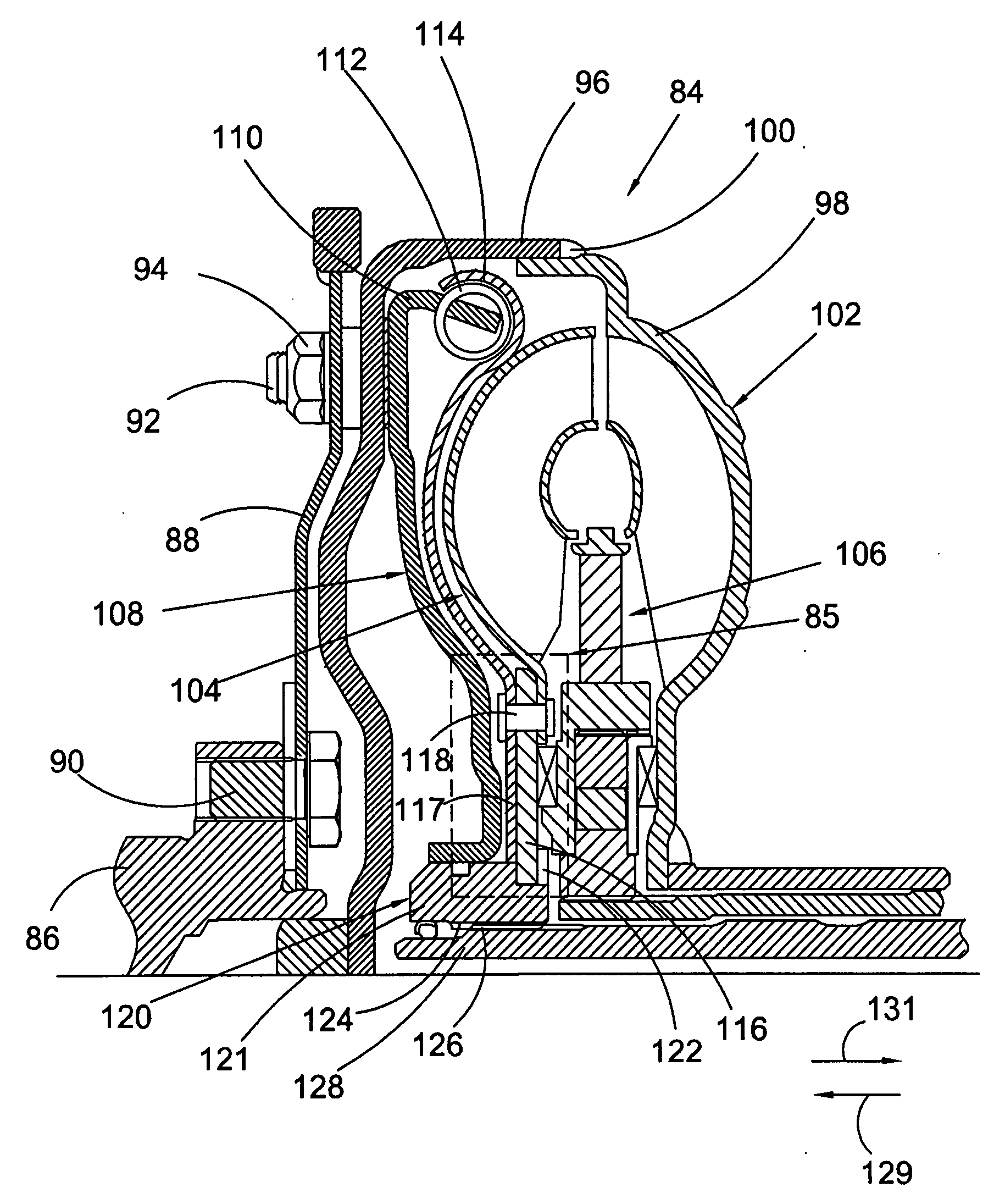
[0017]Yet another object of the invention is to reduce the mass of a torque converter hub.
[0018]A further object of the invention is to provide a hub arrangement that is easy to assemble and which prevents axial displacement between a torque converter turbine and the hub.

Problems solved by technology

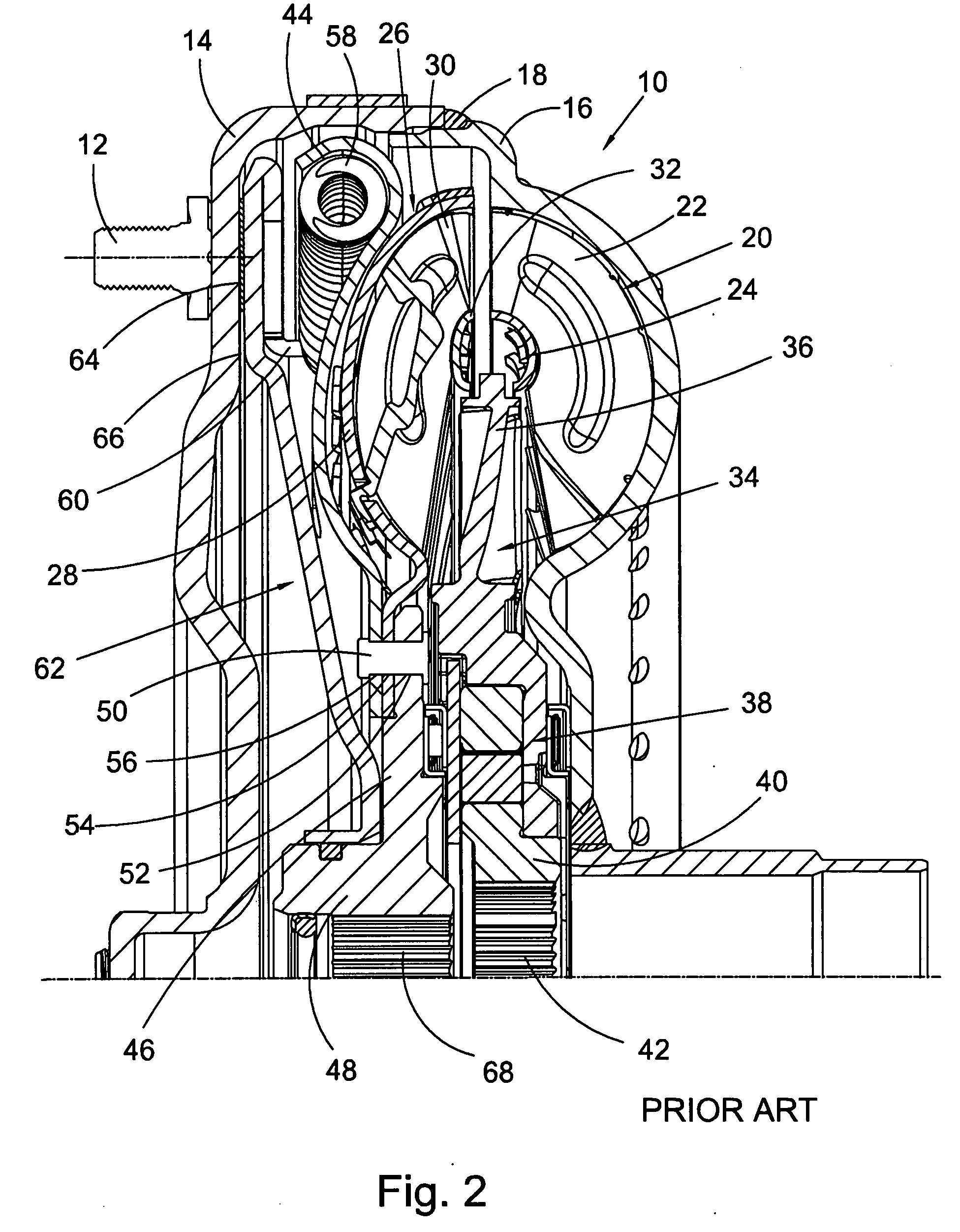
Although using a hub of this type is perhaps the most common means of coupling the turbine to the transmission input shaft, this hub type is expensive to manufacture and introduces a significant amount of mass to the torque converter.
The expense is in part derived from the large quantity of material that must be used to form a hub of this type, as well as the complexity from the added machining and finishing operations that are required.
In short, the extension adds a substantial amount of cost to the hub because it requires more material and a larger die is required for forged or powdered metal pieces.
Added mass can decrease the fuel economy of a vehicle.
Heretofore, tradeoffs between strength and reliability of coupling means, methods of manufacturing component parts and material mass for such means were required.

Method used


Image

  • Apparatus for joining components to a hub
  • Apparatus for joining components to a hub
  • Apparatus for joining components to a hub

Examples


Embodiment Construction

[0035]At the outset, it should be appreciated that like drawing numbers on different drawing views identify identical, or functionally similar, structural elements of the invention. While the present invention is described with respect to what is presently considered to be the preferred embodiment, it is to be understood that the invention as claimed is not limited to the preferred embodiment.

[0036]Furthermore, it is understood that this invention is not limited to the particular methodology, materials and modifications described and as such may, of course, vary. It is also understood that the terminology used herein is for the purpose of describing particular embodiments only, and is not intended to limit the scope of the present invention.

[0037]Unless defined otherwise, all technical and scientific terms used herein have the same meaning as commonly understood to one of ordinary skill in the art to which this invention belongs. Although any methods, devices or materials similar or...


PUM


Abstract

The present invention broadly includes a hub assembly for a torque converter having a hub arranged to rotationally connect to a transmission input shaft and includes first and second radial surfaces, a first plate rotationally connected to a turbine, rotationally connected to the hub, and fixed in a first axial direction by the first surface and a second plate rotationally connected to the first plate and fixed in a second axial direction, opposite the first direction, by the second surface. The hub assembly may include a hub having at least one radially disposed protrusion, the protrusion includes the second radial surface, and the first plate is rotationally connected to the protrusion. The hub may further include a body with a first diameter and the protrusion with a second diameter greater than the first diameter. The first and second radial surfaces may be arranged to axially fix a turbine with respect to the hub, or the first and second radial surfaces may be coplanar. The first plate may be in contact with the first radial surface, or the second plate may be in contact with the second radial surface.

Description

CROSS-REFERENCE TO RELATED APPLICATIONS[0001]This patent application claims the benefit under 35 U.S.C. §119(e) of U.S. Provisional Application No. 60 / 797,518, filed May 4, 2006, which application is incorporated herein by reference.FIELD OF THE INVENTION[0002]The present invention relates generally to torque converters, more particularly, to a torque converter hub, and, more specifically, to an apparatus for joining components to a torque converter hub.BACKGROUND[0003]Hydraulic torque converters, devices used to change the ratio of torque to speed between the input and output shafts of the converter, revolutionized the automotive and marine propulsion industries by providing hydraulic means to transfer energy from an engine to a drive mechanism, e.g., drive shaft or automatic transmission, while smoothing out engine power pulses. A torque converter, arranged between the engine and the transmission, includes three primary components, an impeller, sometimes referred to as a pump, dir...

Claims


Application Information

Patent Timeline
Patent Type & Authority Applications(United States)
IPC IPC(8): F16H41/24
CPCF16D1/0876F16H45/02F16H41/24
Inventor BREES, WILLIAMOLSEN, STEVENSMELTZER, EDWARD
Owner SCHAEFFLER TECH AG & CO KG
Why Eureka
Try Eureka