Highly efficient series string LED driver with individual LED control

a technology of led driver and led control, which is applied in the direction of electric variable regulation, process and machine control, instruments, etc., can solve the problems of low current flow through the other leds which are on and low power dissipation in the switch (current squared times resistance), and achieve high resistance in parallel, low resistance, and high resistance.

Active Publication Date: 2007-11-08
TEXAS INSTR INC
View PDF2 Cites 200 Cited by
  • Summary
  • Abstract
  • Description
  • Claims
  • Application Information

AI Technical Summary

Benefits of technology

[0014] A switch having a high off resistance and low on resistance, such as a field effect transistor (FET), is placed in parallel with each LED in the string. A level shifting driver couples a logic signal to the control terminal of each such switch. When the switch across a particular LED is closed responsive to the control signal applied to the level shifting driver, substantially all the current flows through the switch rather than the LED, and little or no light is emitted. Because the on resistance of the switch is very low, the power dissipated in the switch (current squared times resistance) is also very low. With the switch turned on, the forward voltage drop of the LED it is controlling drops to near zero, since little current is flowing through the LED. However, because the current source is designed to provide constant current over a wide range of output voltages, the current flow through those other LEDs which are on changes very little. When the switch is turned off, it presents a high resistance in parallel with the LED, so substantially all the string current flows through the LED, creating a high brightness level.
[0015] By modulating the duty cycle of each switch, the brightness of each associated LED may be varied smoothly over its full range. If the string of LEDs includes primary color (red, green, blue or RGB) LEDs in close proximity, a wide range of mixed light color may thus be generated. If the series string contains, for example, a plurality of white LEDs as in an architectural lamp, the overall brightness of the lamp may be controlled with high efficiency by controlling the number of LED's in the “on” state.
[0016] Another embodiment of the invention uses a switch to control a group of LEDs rather than a single LED in the string. For example, it may be desirable to increase the brightness of each color in a RGB LED light by employing multiple red, multiple green, and multiple blue LEDs, all in series connection. A single switch across each group of red, green and blue LEDs allows wide ranging control of brightness of that color group, while minimizing the number of drivers.

Problems solved by technology

Because the on resistance of the switch is very low, the power dissipated in the switch (current squared times resistance) is also very low.
However, because the current source is designed to provide constant current over a wide range of output voltages, the current flow through those other LEDs which are on changes very little.

Method used


Image

  • Highly efficient series string LED driver with individual LED control
  • Highly efficient series string LED driver with individual LED control
  • Highly efficient series string LED driver with individual LED control

Examples


Embodiment Construction

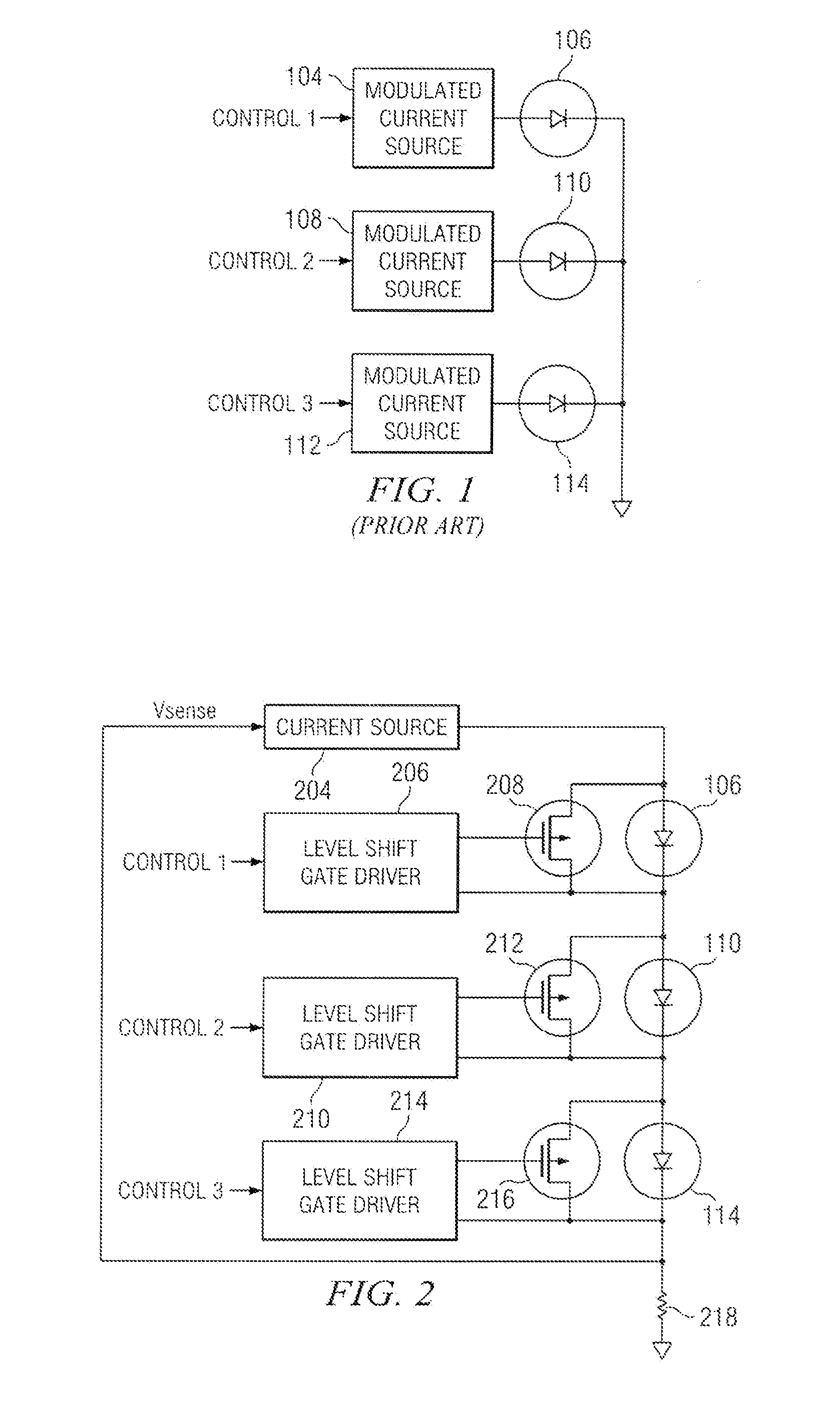
[0027] In FIG. 1 (prior art), a plurality of LEDs 106, 110, 114 each are driven by a MODULATED CURRENT SOURCE 104, 108, 112 respectively. A first terminal of MODULATED CURRENT SOURCE 104 is coupled to a first terminal of LED 106. A second terminal of LED 106 is coupled to ground. A first CONTROL 1 signal is coupled to a second terminal of MODULATED CURRENT SOURCE 104. In a similar fashion, a first terminal of MODULATED CURRENT SOURCE 108 is coupled to a first terminal of LED 110. A second terminal of LED 110 is coupled to ground. A second CONTROL 2 signal is coupled to a second terminal of MODULATED CURRENT SOURCE 108. A first terminal of MODULATED CURRENT SOURCE 112 is coupled to a first terminal of LED 114. A second terminal of LED 114 is coupled to ground. A third CONTROL 3 signal is coupled to a second terminal of MODULATED CURRENT SOURCE 112.

[0028] In operation, current from MODULATED CURRENT SOURCE 104 flows through LED 106 and then to ground, causing LED 106 to generate ligh...


PUM


Abstract

A current source generates, with high efficiency, a current that is substantially constant over a wide range of output voltages. This current is injected into the first end of a series-connected string (hereinafter referred to as string) of LEDs, with the second end of the string connected through a resistor to ground. The voltage developed across this resistor, which is a measure of current flow in the series string, is fed back to the current source, wherein feedback maintains nearly constant current output over a wide range of output voltages. A switch, such as a field effect transistor (FET) is placed in parallel with each LED in the string. A level shift gate driver couples a pulse width modulated control signal to the gate of each FET. When the FET across a particular LED is on, substantially all the current flows through the FET rather than the LED, and little or no light is emitted. Because the one resistance of the FET is very low, the power dissipated in the FET (current squared times resistance) is also very low. With the FET turned on, the forward voltage drop of the LED it is controlling drops to near zero, since little current is flowing through the LED. However, because the current source is designed to provide constant current over a wide range of output voltages, the current flow through the other LEDs in the series string changes little. When the FET is turned off, substantially all of the current flows through the associated LED, turning it on. By modulating the duty cycle of each FET, the brightness of each associated LED may be varied smoothly over its full range.

Description

CROSS-REFERENCE TO RELATED APPLICATIONS [0001] This application claims priority, under 35 U.S.C. §119(e)(1), of U.S. Provisional Application No. 60 / 743,804, entitled “HIGHLY EFFICIENT SERIES STRING LED DRIVER WITH INDIVIDUAL LED CONTROL,” having as its inventors Brant Johnson and James H. Alverti, filed Mar. 27, 2006, and hereby incorporated herein by this reference.BACKGROUND OF THE INVENTION [0002] 1. Field of the Invention [0003] This invention relates generally to driving light emitting diodes (LEDs), and more specifically to efficient duty cycle control of multiple LEDs in a series connected string of such LEDs, so as to control brightness of individual LEDs and color mixture of groups of LEDs. [0004] 2. Description of the Related Art [0005] LEDs are widely used in lighting and display applications due to their high efficiency, long life, ruggedness and compact size. Early LEDs emitted red light, and found usage in calculator and watch displays. The availability of green, yello...

Claims


Application Information

Patent Timeline
Patent Type & Authority Applications(United States)
IPC IPC(8): H05B41/00
CPCH05B33/0818Y02B20/347H05B33/0866H05B33/083H05B45/24H05B45/48Y02B20/30H05B45/3725
Inventor JOHNSON, BRANT TUREALIBERTI, JAMES HENRY
Owner TEXAS INSTR INC
Why Eureka
Try Eureka