Measurement while drilling tool and method

a technology of measuring tool and drilling tool, which is applied in the direction of instruments, borehole/well accessories, surveys, etc., can solve the problems of mwd tools being expensive tools, expensive wells, and taking a significant amount of time to plan, so as to eliminate maintenance problems, reduce the length of the tool, and reduce the cost

Inactive Publication Date: 2007-11-08
NAVIGATE ENERGY SERVICES
View PDF10 Cites 8 Cited by
  • Summary
  • Abstract
  • Description
  • Claims
  • Application Information

AI Technical Summary

Benefits of technology

[0011] An advantage of the present invention is that the design allows for fewer parts and a shorter tool length. Another advantage is that the components of the system are designed in modules, wherein the modules can be replaced with a new module. Another advantage is that no field service technicians are needed, eliminating maintenance problems. Because the tool is designed to go straight from manufacturing to the rig, much higher utilization rates will be achieved.
[0012] A feature of the present invention includes the annular main valve, wherein the funnel shape of the main valve contains all violent, turbulent flow caused by pulsers, and in doing so, it contains all the erosion within its surface that is made of very hard ceramic or tungsten carbide material. Another feature is the ball control valve that utilizes a poppet valve constructed of a separate ball and shaft that allows the ball to seat perfectly by eliminating concentricity issues. Another feature is that the present design is very well suited for fluids with high solid contents.
[0013] Yet another feature is the annular screen element that allows a large inlet area for a relatively small axial height, thus allowing the overall length to be significantly shorter than current designs. Still yet another feature is that the annular solenoid doughnut shape provides the geometry best suited to minimize overall valve length. Another feature is the annular control valve. Still yet another feature is the control valve ball seat, pilot driven main valve, and exit that are nearly aligned to minimize axial packaging requirements. Thus, the shortest (minimum axial length) possible valve is obtained.

Problems solved by technology

The wells are expensive and take a significant amount of time to plan.
MWD tools are expensive tools due to their complexity.
The tools are designed for a lifetime of 5-7 years, and the tools are routinely made of expensive materials and electronics which require a lot of maintenance by highly trained personnel.
As the use of MWD and LWD tools expanded, several problems have become evident.
One problem is that maintenance requires very high levels of training.
Another problem is that the maintenance facilities require large spaces and expensive testing equipment.
In one study, it was found that a MWD tool string spends less than 90 days a year in a well, and the maintenance and logistics cost of a MWD tool can amount to 50% of the annual expense of the system.

Method used


Image

  • Measurement while drilling tool and method
  • Measurement while drilling tool and method
  • Measurement while drilling tool and method

Examples


Embodiment Construction

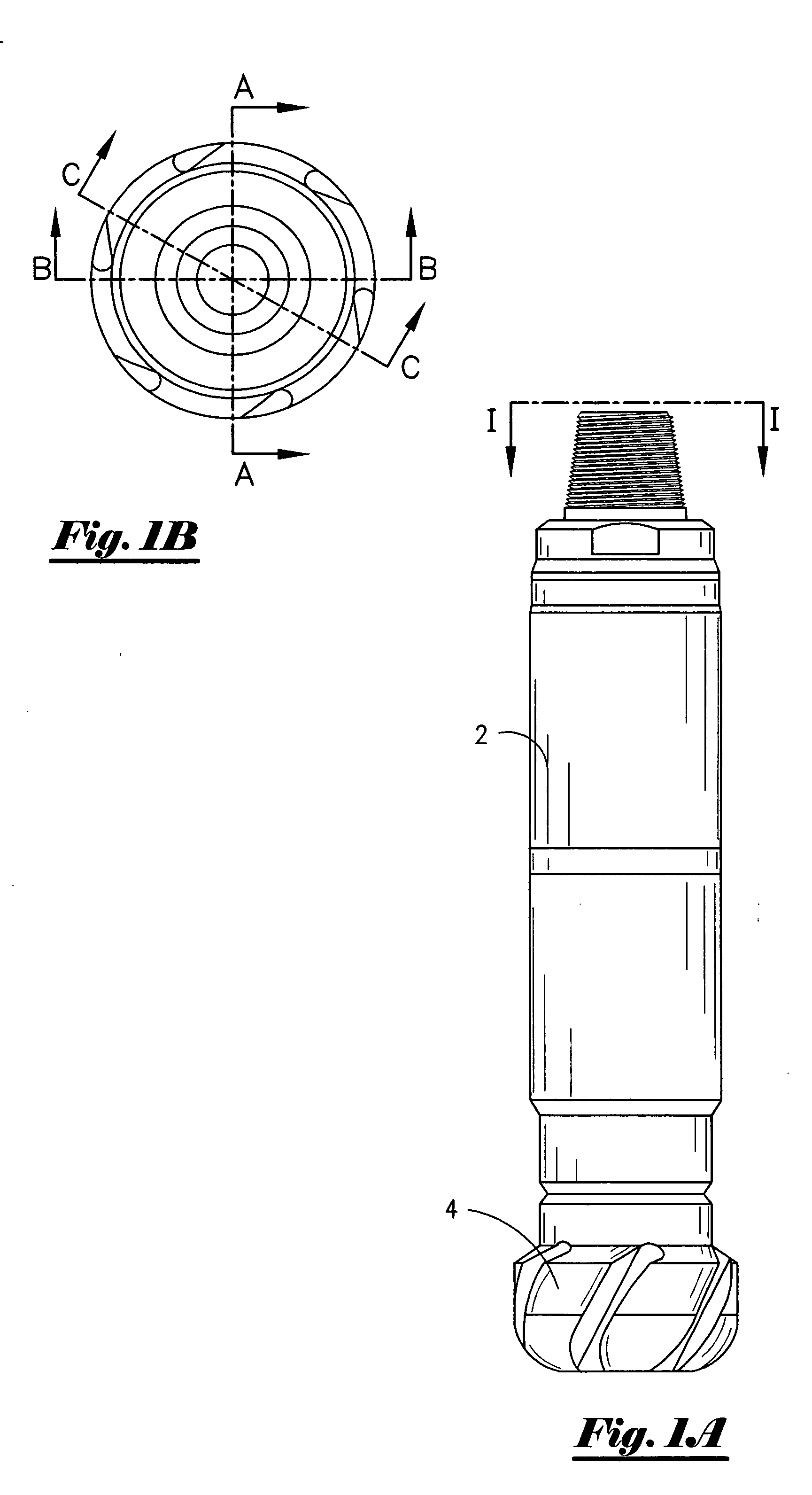
[0025] Referring now to FIG. 1A, a perspective view of the drill collar housing 2 containing the down hole apparatus and drill bit 4. As understood by those of ordinary skill in the art, the drill collar housing 2 is connected to the drill bit 4. FIG. 1B is a perspective view of the drill collar housing seen in FIG. 1A taken from view I-I. More specifically, FIG. 1B depicts the lines A-A, B-B, and C-C which will described in more detail later in the application.

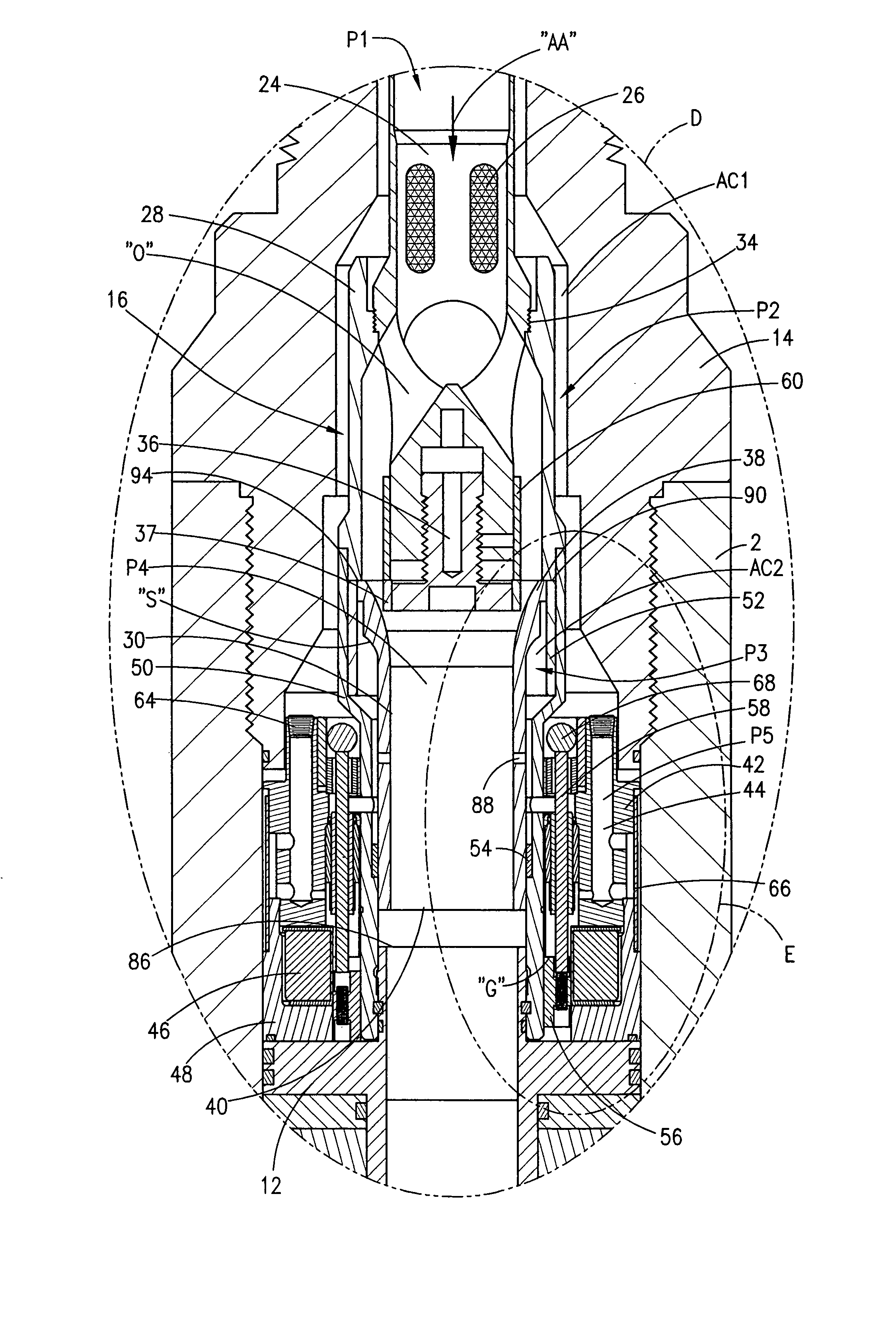
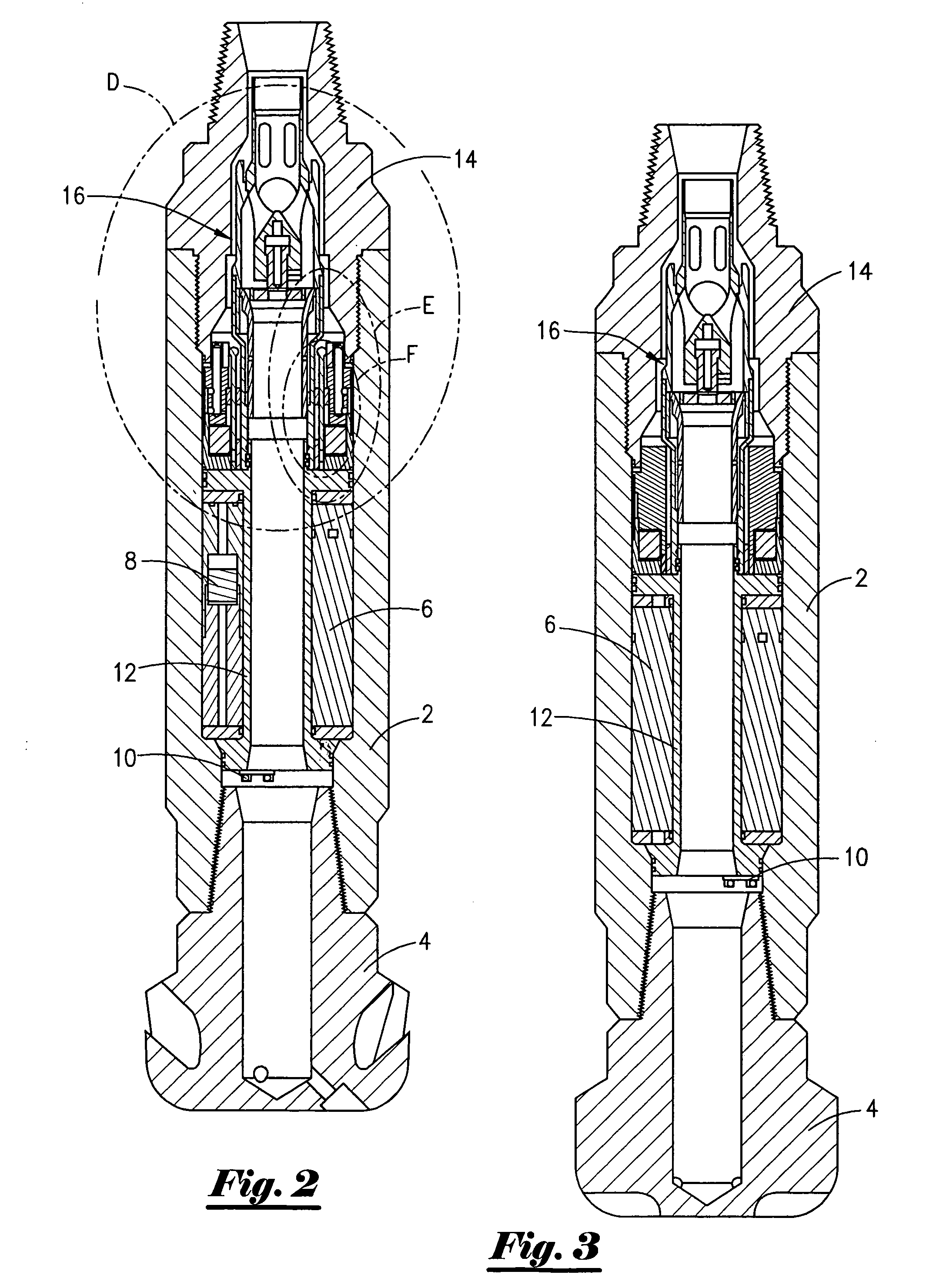
[0026] Referring now to FIG. 2, a cross-sectional view of the drill collar housing containing the down hole apparatus, drill collar housing 2 and drill bit 4 seen in FIG. 1A taken along line A-A of FIG. 1B will now be described. It should be noted that like numbers appearing in the various drawings refer to like components. More specifically, FIG. 2 depicts the battery and electronics section 6 to power and control the tool. The electronics section 6 includes a controller for processing collected down hole data, storing the ...


PUM


Abstract

An apparatus for telemetering a downhole parameter from a well. The apparatus comprises a housing having a bore. The apparatus further comprises an annular main valve with an enlarged end positioned within the bore, with the main valve having a center of axis. A restrictor is concentrically disposed within the bore, the restrictor configured to define an annular passage with the main valve. The apparatus also includes: a pressure device for supplying hydraulic pressure to the main valve; a control valve, operatively associated with the restrictor member, for controlling pressure to the main valve; and a solenoid control valve assembly for activating the control valve. In one preferred embodiment, the solenoid control valve assembly comprises a controller for emitting an electrical signal, a coil that receives the electrical signal and generates a magnetic field, a solenoid static pole receptive to the generated magnetic field, and a solenoid moving pole responsive to the magnetic field so that the solenoid moving pole moves in a direction towards the solenoid static pole. A method for communicating a downhole parameter is also disclosed.

Description

BACKGROUND OF THE INVENTION [0001] This invention relates to a measurement while drilling tool. More specifically, but without limitation, this invention relates to an apparatus and method for telemetering a down hole parameter from a well. [0002] Operators drill wells many thousands of feet in the search for hydrocarbons. The wells are expensive and take a significant amount of time to plan. Operators find it important to obtain data about the various subterranean reservoirs once the actual drilling begins. Thus, measurement while drilling (MWD) tools have been developed that gather information about the subterranean reservoirs and telemetry the data to the surface. Engineers and geologist can then use this data in an effort to understand the formations and make plans on completion, sidetracking, abandoning, further drilling etc. [0003] MWD tools are expensive tools due to their complexity. The tools are designed for a lifetime of 5-7 years, and the tools are routinely made of expe...

Claims


Application Information

Patent Timeline
Patent Type & Authority Applications(United States)
IPC IPC(8): G01V3/00H04H9/00H04H60/31
CPCE21B47/187E21B47/24
Inventor HARVEY, PETER R.
Owner NAVIGATE ENERGY SERVICES
Why Eureka
Try Eureka