Method And Apparatus For Single Input, Multiple Output Selection Diversity Aiding Signal Tracking

a signal tracking and multiple output technology, applied in electrical equipment, synchronisation arrangements, wireless commuication services, etc., can solve the problems of significant complexity of timing and frequency acquisition using conventional phase locked loop (pll)-based designs, limited utility of high-order plls in practical systems, and increase complexity. , to achieve the effect of reducing complexity

Inactive Publication Date: 2007-11-08
HARRIS CORP
View PDF14 Cites 13 Cited by
  • Summary
  • Abstract
  • Description
  • Claims
  • Application Information

AI Technical Summary

Benefits of technology

[0028] In accordance with the present invention, this obscuration problem is effectively circumvented by employing a spatially diverse antenna arrangement, that places multiple antennas at spaced apart locations affording different views of the transmitter (satellite), in combination with a reduced complexity, (view of the transmitter obscuration) ‘information’ or ‘knowledge’-aided mechanism to select which one of these spatially diverse antennas is to be used by the receiver to receive downlink communication signals from the satellite.

Problems solved by technology

In a system wherein there is relative motion between the transmitter and receiver, such as in a satellite or airborne communication system, cell phone system, and the like, this problem becomes more complex, due to kinematic parameters associated with motion, particularly, acceleration by either or both of the transmitter or receiver.
As a result, for frequency-hopped signals, the signals will appear to have time-varying Doppler, which significantly complicates timing and frequency acquisition using conventional phase locked loop (PLL)-based designs.
Unfortunately, high-order PLLs have limited utility in practical systems due to difficulty in design and stabilization.
In addition, the use of global positioning system (GPS) data would be inadequate, since data for time and frequency corrections must be exceedingly accurate, especially if the data source to be tracked has a relatively high data rate, not to mention the negative impact on receiver complexity.
As pointed out above, PLL-based mechanisms for deriving timing and frequency information used for demodulation cannot readily accommodate such measurement sequence variations and will fail when applied to time and frequency hopped sync signals, particularly in environments subject to kinematic influences that include acceleration.
Although prior art literature has suggested that Kalman filters may be used in the track state of a communication link, none has addressed the relationship between communication synchronization parameters (time and frequency offsets) and kinematic variables, which is the basic problem in a satellite downlink environment, where time difference and range change rate are unknown.
However, such schemes will not work in practice for the time and frequency acquisition and tracking problem encountered in a dynamic communication system of the type described above, as their hardware implementations would occupy an unacceptable amount of semiconductor real estate to fit within a few ASICs, and would consume an extraordinary amount of power.
Moreover, if implemented digitally, their associated processors could not process data fast enough to realize a viable solution for data rates of practical interest.
In this way, frequency errors will manifest themselves as velocity errors, which correspond to the error in the rate of change of range R′, and time errors will manifest themselves as LOS range errors.
Velocity errors are scaled frequency errors.
Unfortunately, such an unobstructed view cannot be guaranteed in every environment in which the receiver may be used.
One issue related to obstruction is that the reception system might become overly sensitized (e.g. AGC—automatic gain control—is increased) allowing numerous “false detects” to occur.
As another non-limiting example, a modification of the ship's superstructure adjacent to where the antenna is mounted may cause the antenna's view of the satellite to be blocked.
Unfortunately, in this case, the detections are noise-only, and hence provide no time / frequency information, and will serve only to mis-adjust the reception system.

Method used


Image

  • Method And Apparatus For Single Input, Multiple Output Selection Diversity Aiding Signal Tracking
  • Method And Apparatus For Single Input, Multiple Output Selection Diversity Aiding Signal Tracking
  • Method And Apparatus For Single Input, Multiple Output Selection Diversity Aiding Signal Tracking

Examples


Embodiment Construction

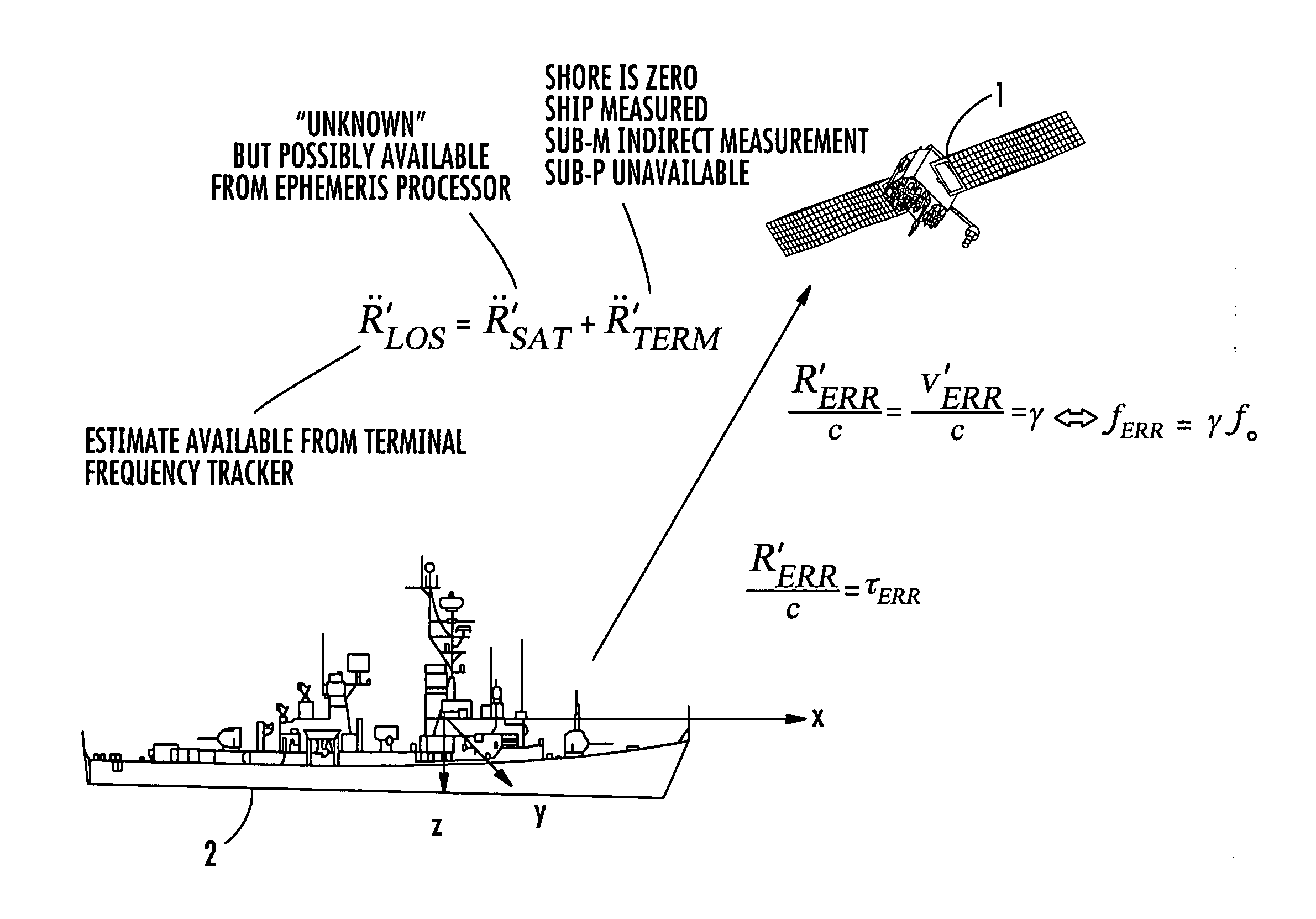
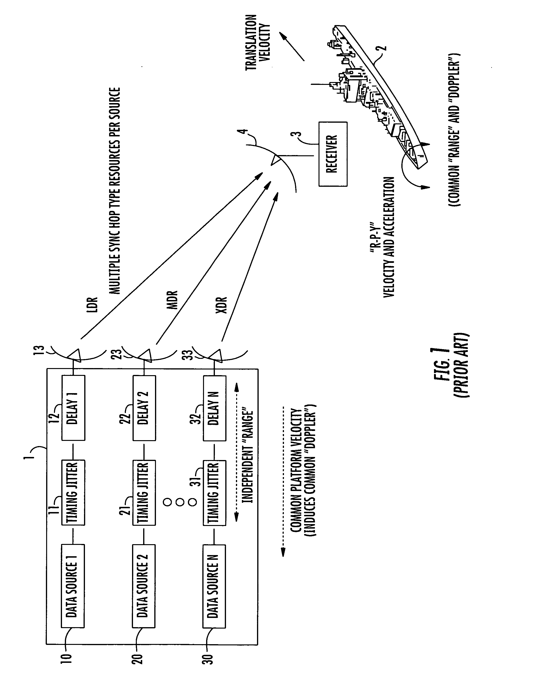
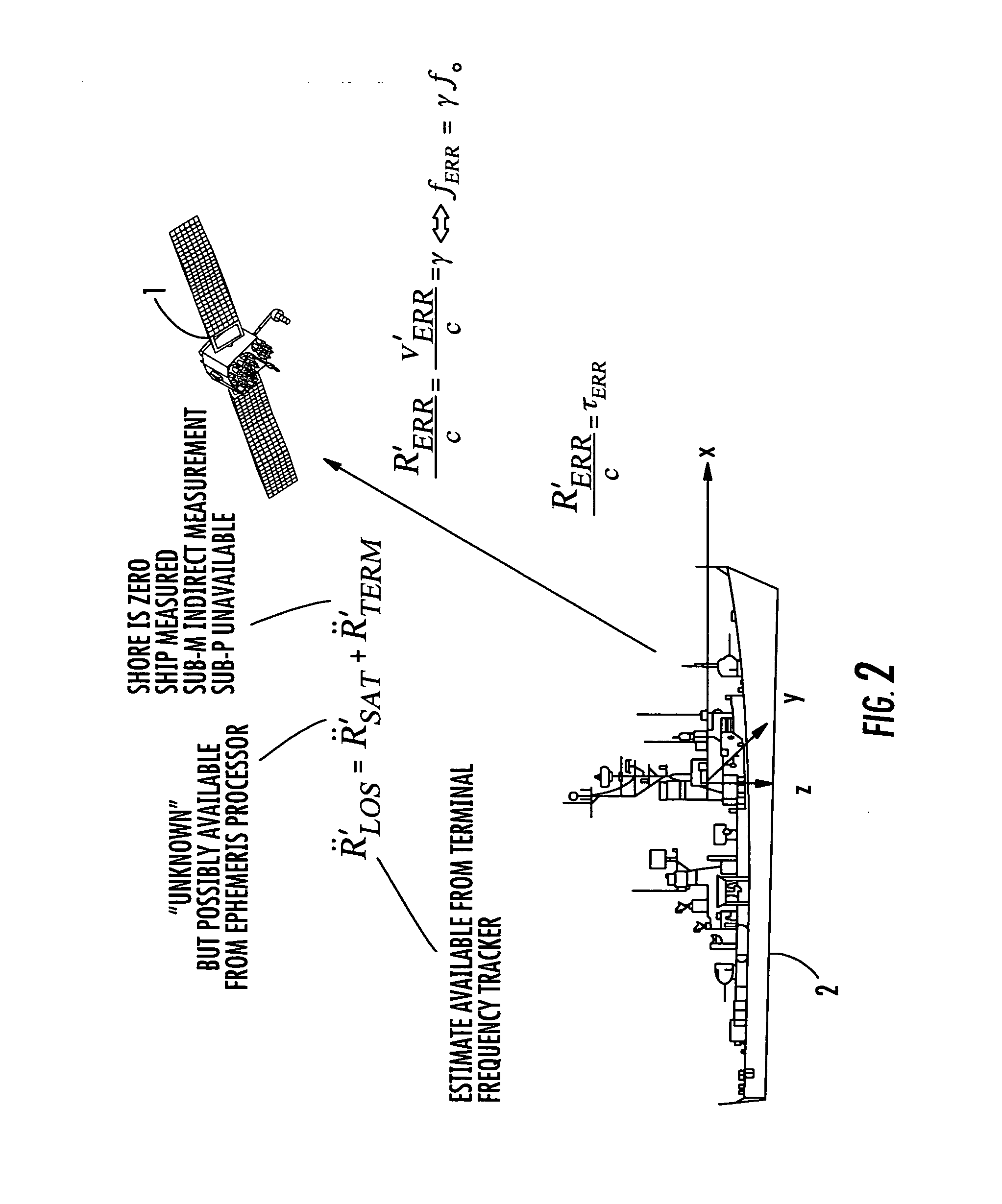
[0044] Before describing, in detail, the structure and operation of the ‘knowledge’-aided antenna selection mechanism in accordance with the present invention, it should be observed that the invention resides primarily in a prescribed arrangement of conventional communication signal collection, processing circuits and components, and supervisory digital control circuitry that controls the operations of these circuits and components, and not in the details thereof. Consequently, in the drawings, such circuits and components, and the manner in which they are interfaced with various communication equipments have, for the most part, been illustrated by readily understandable block diagrams, which show only those specific details that are pertinent to the present invention, so as not to obscure the disclosure with details which will be readily apparent to those skilled in the art having the benefit of the description herein. Thus, the diagrammatic illustrations are primarily intended to ...


PUM


Abstract

An obscuration ‘information’-aided mechanism controls which of a plurality of spatially diverse antennas having different views of a satellite is to be coupled to a receiver, by comparing respective spatial maps of quantized visibility values, representative of the abilities of the antennas to see the satellite, with information representative of the pointing directions of the antennas. The antenna having the best view of the satellite is selected.

Description

CROSS-REFERENCE TO RELATED APPLICATIONS [0001] The present application is a continuation-in-part of co-pending U.S. patent application Ser. No. 11 / 384,868, filed Mar. 20, 2006, by E. Beadle et al, entitled: “Time / Frequency Recovery of a Communication Signal in a Multi-Beam Configuration Using a Kinematic-Based Kalman Filter and Providing a Pseudo-Ranging Feature” (hereinafter referred to as the '868 application), assigned to the assignee of the present application and the disclosure of which are incorporated herein.GOVERNMENT LICENSE RIGHTS [0002] The U.S. Government has a paid-up license in this invention and the right in limited circumstances to require the patent owner to license others on reasonable terms as provided for by the terms of contract No. AEHF-NMT N00039-04-C-0011.FIELD OF THE INVENTION [0003] The present invention relates in general to communication systems and subsystems thereof, wherein either the transmitter terminal and / or receiver terminal may be a mobile platfo...

Claims


Application Information

Patent Timeline
Patent Type & Authority Applications(United States)
IPC IPC(8): H04B7/185
CPCH04B7/18513H04B7/18589H04W56/0075H04B7/2681H04W56/0035H04B7/2675
Inventor BEADLE, EDWARD R.DISHMAN, JOHN F.
Owner HARRIS CORP
Why Eureka
Try Eureka