
Synchronous shift execution for hybrid transmission

a technology of hybrid transmission and transmission shift, applied in the direction of motor/generator/converter stopper, process and machine control, external condition input parameters, etc., to achieve the effect of reducing the motive torqu

Inactive Publication Date: 2007-11-08
GM GLOBAL TECH OPERATIONS LLC
View PDF11 Cites 160 Cited by
  • Summary
  • Abstract
  • Description
  • Claims
  • Application Information

AI Technical Summary

Benefits of technology

The patent text describes a method and system for shifting gears in a powertrain system of a vehicle. The system includes a transmission with multiple torque-generative devices, such as electric motors and an internal combustion engine, and a control system to manage the transmission. The control system uses a computer program to execute the shift from initial gear to final gear in the transmission. The technical effects of the invention include reducing reactive torque of the first torque-transfer device, deactivating the first torque-transfer device when the reactive torque is low, increasing torque capacity of the second torque-transfer device, and shifting from mode operation to final fixed gear ratio based on external conditions or operator demand. The invention provides a more efficient and synchronous shift process for powertrain systems.

Problems solved by technology

An ongoing challenge with any shifting scheme is to have a gear shift event which may be discernible to an operator, but not displeasing.

Method used


Image

  • Synchronous shift execution for hybrid transmission
  • Synchronous shift execution for hybrid transmission
  • Synchronous shift execution for hybrid transmission

Examples


Embodiment Construction

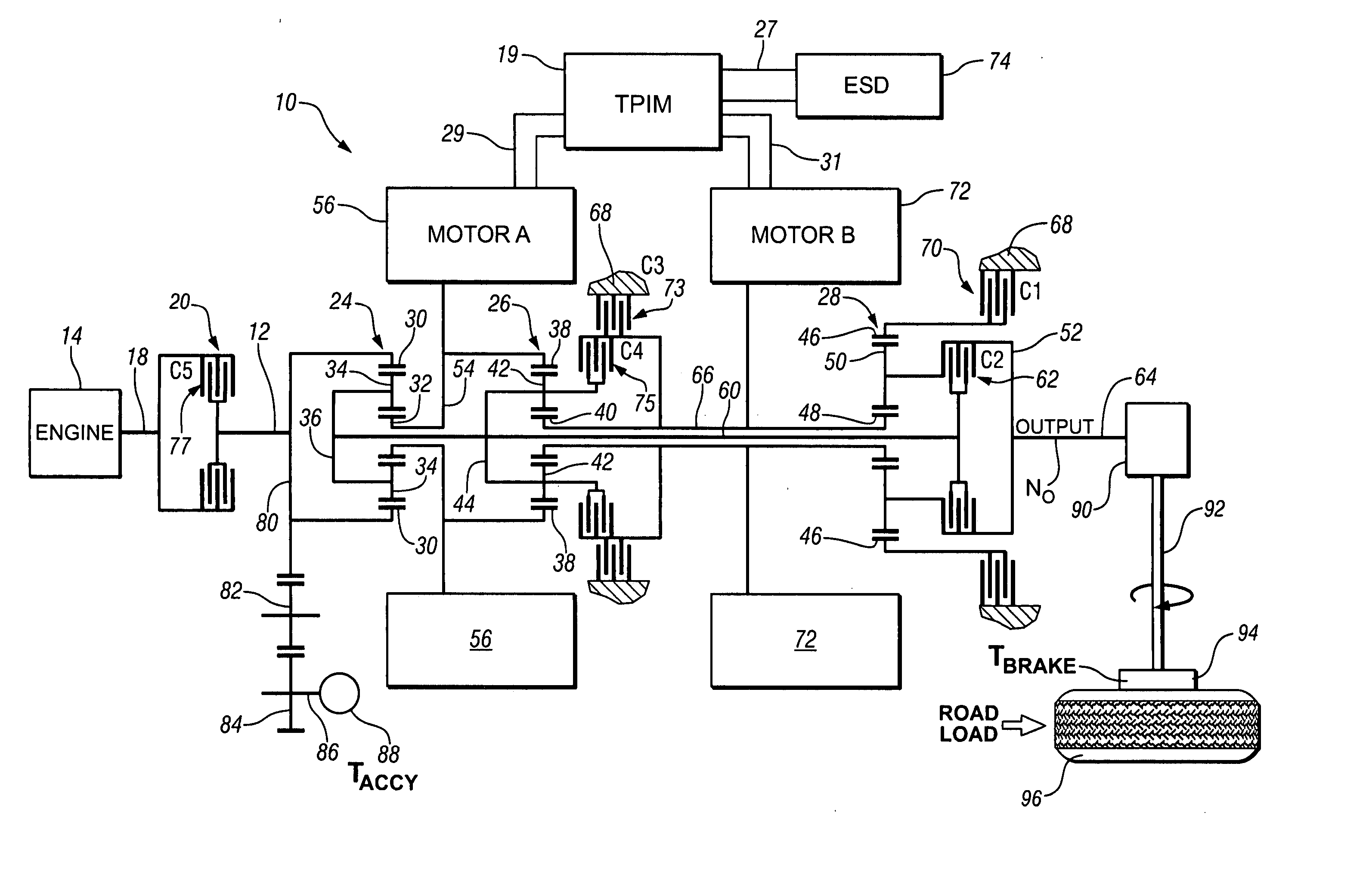
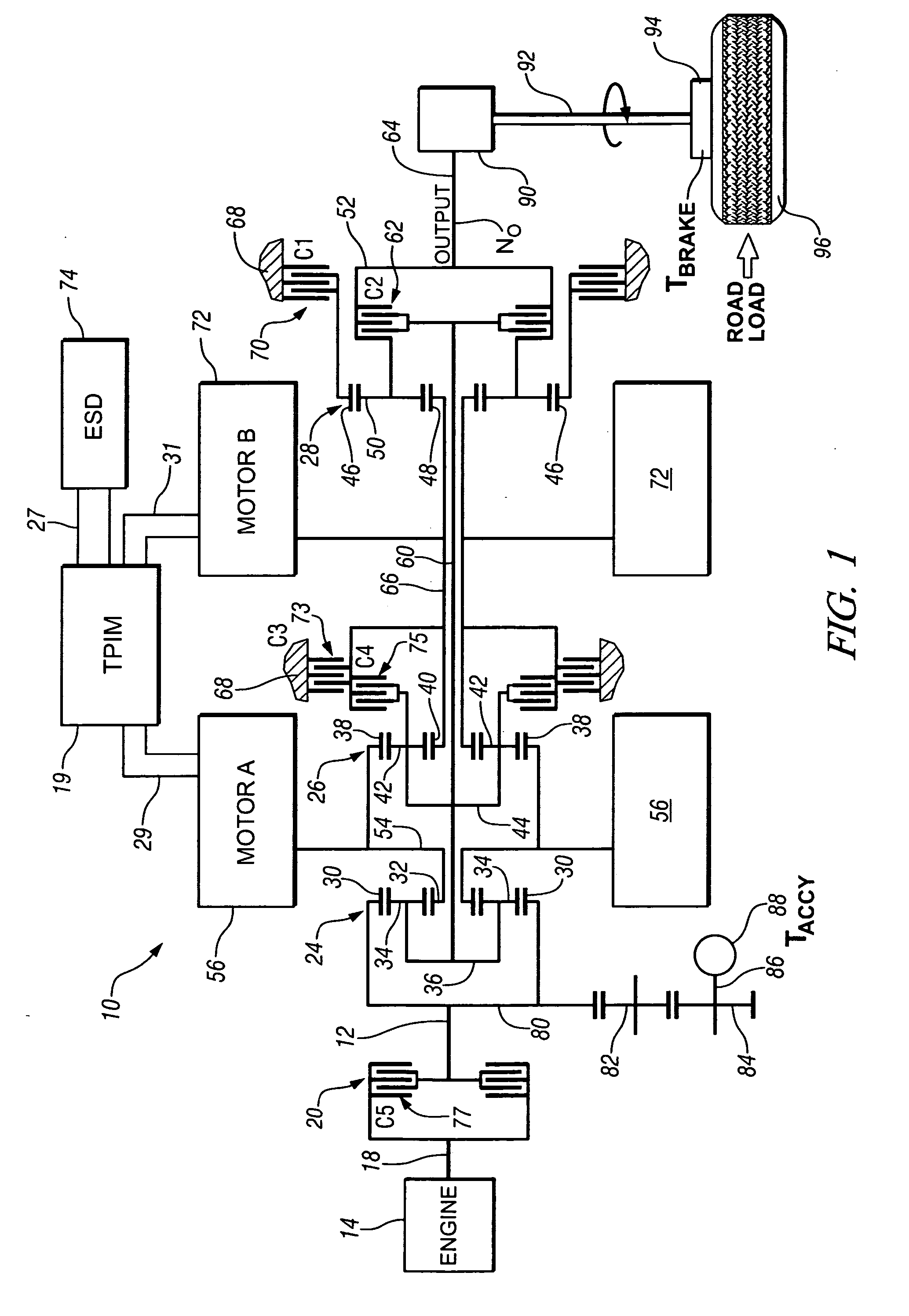
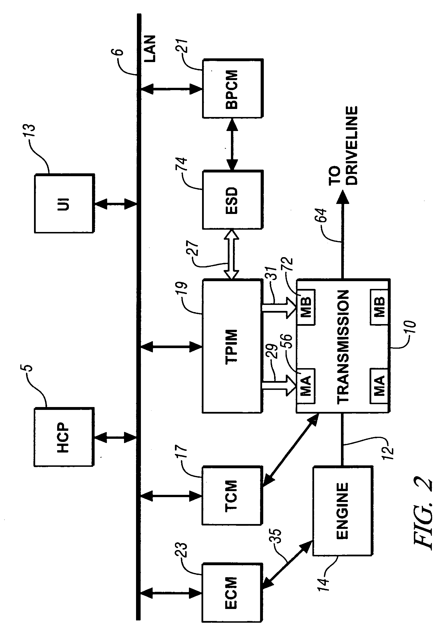
[0027] Referring now to the drawings, wherein the showings are for the purpose of illustrating the invention only and not for the purpose of limiting the same, FIGS. 1 and 2 show a system comprising an engine 14, transmission 10, control system, and driveline which has been constructed in accordance with an embodiment of the present invention.

[0028] Mechanical aspects of exemplary transmission 10 are disclosed in detail in commonly assigned U.S. Patent Application Publication No. U.S. 2005 / 0137042 A1, published Jun. 23, 2005, entitled Two-Mode, Compound-Split, Hybrid Electro-Mechanical Transmission having Four Fixed Ratios, which is incorporated herein by reference. The exemplary two-mode, compound-split, electromechanical hybrid transmission embodying the concepts of the present invention is depicted in FIG. 1, and is designated generally by the numeral 10. The hybrid transmission 10 has an input member 12 that may be in the nature of a shaft which may be directly driven by an eng...


PUM


Abstract

An apparatus and method are provided to execute synchronous shifting in a powertrain system having multiple torque-generative devices each operable to independently supply motive torque to the transmission device. The exemplary transmission device comprises a two-mode, compound-split, hybrid electromechanical transmission. Operation includes operating in an initial fixed gear ratio, operating the transmission in a mode operation, and, operating the transmission in a final fixed gear ratio. The control system reduces reactive torque of a clutch activating the initial gear, and deactivates the first torque-transfer device when the reactive torque is less than a predetermined value. It determines that speed of an input shaft to the transmission is substantially synchronized with a rotational speed of the second torque-transfer device, and actuates the second torque-transfer device.

Description

TECHNICAL FIELD [0001] This invention pertains generally to hybrid powertrain control systems, and more specifically to executing transmission shifts. BACKGROUND OF THE INVENTION [0002] Various hybrid powertrain architectures are known for managing the input and output torques of various prime-movers in hybrid vehicles, most commonly internal combustion engines and electric machines. One such hybrid powertrain architecture comprises a two-mode, compound-split, electromechanical transmission which utilizes an input member for receiving power from a prime mover power source and an output member for delivering power from the transmission. First and second motor / generators are operatively connected to an energy storage device for interchanging electrical power between the storage device and the first and second motor / generators. A control unit is provided for regulating the electrical power interchange between the energy storage device and the first and second motor / generators. The cont...

Claims


Application Information

Patent Timeline
Patent Type & Authority Applications(United States)
IPC IPC(8): G06F17/00
CPCB60K1/02Y10T477/32B60K6/445B60K6/547B60L2240/423B60L2240/441B60L2240/445B60L2240/486B60W10/02B60W10/06B60W10/08B60W10/115B60W20/00B60W2510/025B60W2510/0638B60W2510/0671B60W2510/0676B60W2540/16B60W2550/12B60W2550/142B60W2710/027B60W2710/0666B60W2710/083F16H3/728F16H61/061F16H61/686F16H2037/106F16H2200/201F16H2200/2041Y02T10/6286Y02T10/642Y02T10/6239F16H2059/663Y10T477/27Y10T477/26Y10T477/328Y10T477/23Y10T477/337Y10T477/33Y10T477/333Y10T477/30B60K6/365B60W2552/15B60W2555/20Y02T10/62Y02T10/64B60W2050/0006B60W20/40
Inventor SAH, JY-JEN F.
Owner GM GLOBAL TECH OPERATIONS LLC
Learn More