Failsafe injected adhesive joint

a technology of injected adhesives and adhesive joints, which is applied in the direction of machines/engines, other domestic objects, mechanical equipment, etc., can solve the problems of difficult certification of the use of adhesive bonds in aircraft and other primary structures, and considerable effort in both manufacturing and inspection

Active Publication Date: 2007-11-15
LOCKHEED MARTIN CORP
View PDF20 Cites 62 Cited by
  • Summary
  • Abstract
  • Description
  • Claims
  • Application Information

AI Technical Summary

Benefits of technology

[0011]Injecting adhesive from outside the structure into a structural bonded joint is a vast improvement of current techniques. Fitup and surface preparations of the bonding surfaces are no longer critical. The only critical processes that must be verified is that the adhesive has properly filled out all the recesses and is fully cured. This verification is easy to do, since the adhesive samples can be taken from the exposed injection ports, and filling of the cavities can be verified by X-ray or techniques commonly used for structures.
[0012]Also, the invention allows dry assembly with sequential bonding of individual joints. This feature allows large structures to be joined over a period of time, without regard for the cure time of the adhesive.

Problems solved by technology

This bond is critical, and requires considerable effort in both manufacturing and inspection.
Despite the best efforts, use of adhesive bonds in aircraft and other primary structures is very difficult to certify, due to the catastrophic failure mode of a debonded joint.
This is difficult to accomplish at times, leaving spaces or areas that do not have adhesive.

Method used


Image

  • Failsafe injected adhesive joint
  • Failsafe injected adhesive joint
  • Failsafe injected adhesive joint

Examples


Embodiment Construction

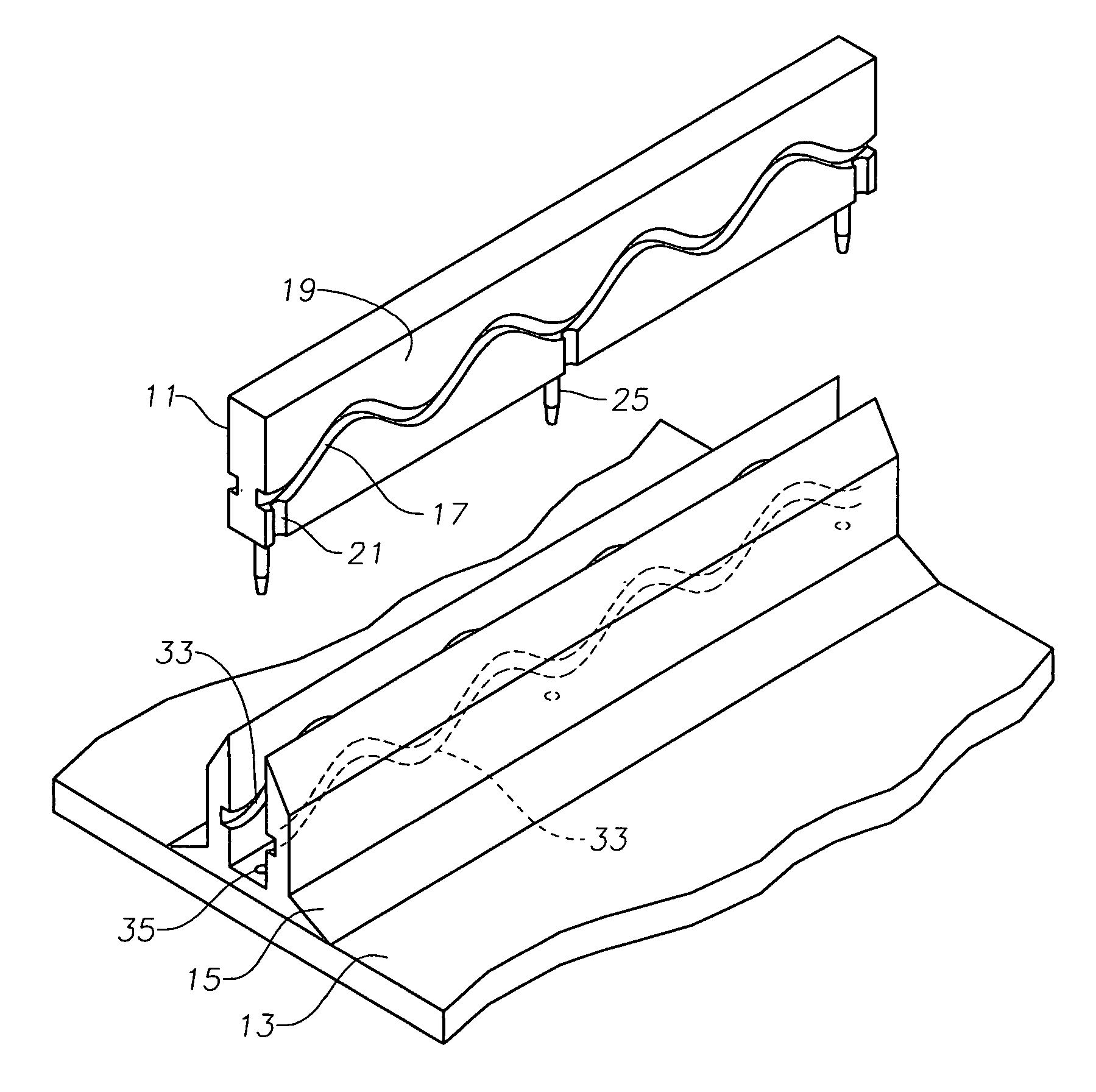
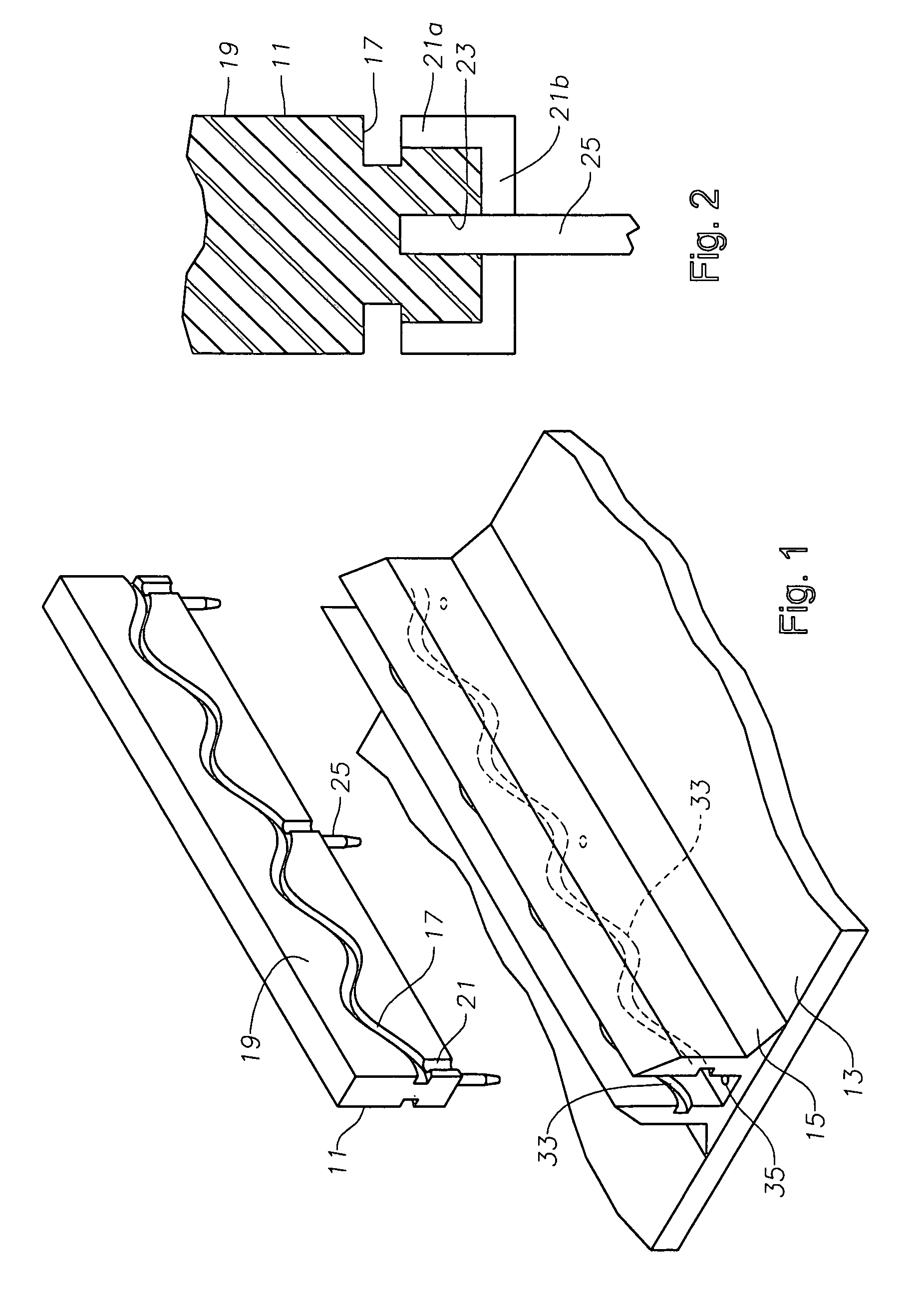
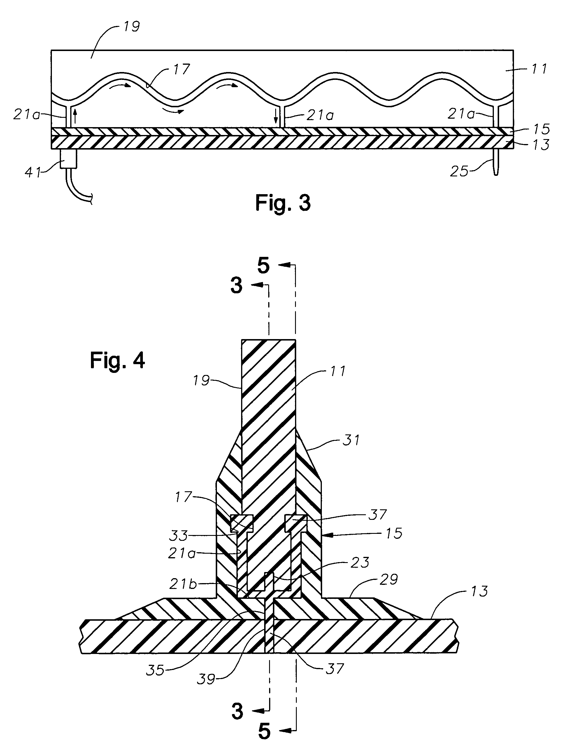
[0019]Referring to FIG. 1, a structural member 11 is shown being joined to a second member 13, which typically comprises the skin of an aircraft. In one example, an interface member 15 provides an interface to bond structural member 11 with skin 13. In one embodiment, interface member 15 comprises a woven preform, however other members could alternately be used.

[0020]Structural member 11 may comprise a variety of aircraft frame components such as a spar or beam of a wing or fuselage, a bulkhead, or a bracket. The word “structural” is used for convenience and not in a limiting manner. In this embodiment, both structural member 11 and skin 13 are formed of laminated resin composite material. That is, each is formed of multiple layers of fiber, such as carbon, laid up one upon the other. Some of the layers may be unidirectional and other layers woven or otherwise configured. Alternatively, structural member 11 could be a metal. Preferably, structural member 11 and skin 13 are cured pri...


PUM

PropertyMeasurementUnit
apart distancesaaaaaaaaaa
lengthsaaaaaaaaaa
shear loadaaaaaaaaaa

Abstract

A composite member is joined to another composite or noncomposite member, using liquid or paste adhesive resin that cures in the joint. The joint is configured in such a way that the adhesive forms an interlocking key within recesses in the joined members that prevents joint disassembly once the adhesive has cured and hardened. Both of the members are provided with recesses extending along their lengths in the joint. The recesses register with each other to define a cavity and may undulate. The recessed are designed in such a way as to take the full load capability if the joint, even if there is no adhesion to the joined members. Adhesive is injected into the cavity through injection ports spaced periodically along the length of the joint.

Description

FIELD OF THE INVENTION[0001]This invention relates in general to a method for joining structural composite parts or composite to noncomposite parts using an adhesive injected into the joint with failsafe featuresBACKGROUND OF THE INVENTION [0002]One method of joining two structural members together is by the use of an adhesive at the interface between the two members. The adhesive typically transfers shear load between the members via an adhesive bond. This bond is critical, and requires considerable effort in both manufacturing and inspection. Despite the best efforts, use of adhesive bonds in aircraft and other primary structures is very difficult to certify, due to the catastrophic failure mode of a debonded joint. The only proven way around this pervasive problem is to bolt the bonded joint together with mechanical fasteners, which removes many advantages of the bonded joint, particularly when the joined members are composite.[0003]It is important during the bond assembly proces...

Claims


Application Information

Patent Timeline
Patent Type & Authority Applications(United States)
IPC IPC(8): B29C65/00
CPCB29C65/542Y10T156/1089B29C66/221B29C66/43441B29C66/712B29C66/721B29L2031/3076F16B11/006B29C65/7855B29C65/483B29C66/112B29C66/12441B29C66/131B29C66/474B29C65/00B29C66/7212B29C66/72141B29K2307/04
Inventor MALIS, MICHAEL B.
Owner LOCKHEED MARTIN CORP
Why Eureka
Try Eureka