Limited loss laminar flow dampers for heating, ventilation, and air conditioning (HVAC) systems

a technology of laminar flow and heating, which is applied in the direction of ventilation systems, lighting and heating apparatuses, heating types, etc., can solve the problems of reducing worker productivity, biological problems in indoor environments that have received considerable attention, and the operation of hvac systems is affected by biological contamination by bacteria, molds, viruses, etc., to achieve sufficiently accurate flow measurement, facilitate relatively simple flow measurement techniques, and inhibit inadvertent pressure drop and turbulence in flows

Inactive Publication Date: 2007-11-15
KARAMANOS JOHN C
View PDF10 Cites 43 Cited by
  • Summary
  • Abstract
  • Description
  • Claims
  • Application Information

AI Technical Summary

Benefits of technology

[0024] Improved HVAC devices, systems, and / or methods include dampers for controlling the flow of air or other gasses through an HVAC duct, often while inhibiting turbulence within the duct and / or pressure loss within the duct at least when the damper is in an open flow configuration. By limiting flow turbulence, these embodiments may facilitate relatively simple flow measurement techniques, allowing sufficiently accurate flow measurements without, for example, having to resort to a multi-axis flow sensor. Embodiments of such dampers may employ a two-part damper arrangement. In many embodiments, flow will travel through the middle of the damper uniformly and with a laminar flow. One or more small, relatively unobtrusive sensors (optionally being wireless) can be included for controlling operation of the damper, the sensor(s) optionally measuring the distance between damper elements, sound, air flow, or the like, with such sensor(s) / damper combination inhibiting inadvertent pressure drop and turbulence in flows through the damper. The damper elements may optionally comprise airfoil cross-sections, with alternative dampers having a resilient helical configuration that can choke down flow by inducing a vortex in the flow, allowing static pressure regain to occur within the duct system. Such dampers may have control advantages, enhance energy efficiency, limit noise, and / or provide enhanced performance characteristics.

Problems solved by technology

One risk which must be addressed in designing and operating HVAC systems is that of biological contamination by bacteria, molds, and viruses.
In recent years, biological problems in indoor environments have received considerable attention.
Poor indoor air quality (“IAQ”) and the spread of infectious disease through a HVAC system, at a minimum, can reduce worker productivity and increase absenteeism.
Even more alarming is the potential liability for illnesses suffered by workers due to poor IAQ.
Even if contamination by molds and bacteria doesn't affect workers, their growth within HVAC system equipment creates maintenance problems which are very costly to correct.
Left uncorrected, these problems exacerbate and, at a minimum, eventually reduce system's heat transfer efficiency.
Builders or contractors typically use ladders or scaffolding to reach areas where piping is routed so installation may be cumbersome.
Furthermore, conditions existing at construction sites and the number of differing types of components used in assembling a HVAC system render cataloging those components impractical if not impossible.
Due to the use of such light material, casings are easily damaged during shipping to a building site and during installation into the HVAC system.
Furthermore, present practices and equipment are poorly adapted for swiftly constructing a high quality HVAC system that is easily commissioned.
Due to the use of this light material, casings are easily dented or bent during installation.
Furthermore, terminal units assembled at a construction site generally differ from one another due to assembly by different craftsmen, and insufficient use of identical components in assembling each terminal unit.
Due to conditions existing at construction sites and the number of differing types of components used in assembling a HVAC system, cataloging the components used in assembling the system is impractical.
Lastly, construction sites generally lack any facilities for individually pre-testing building components, such as terminal units, assembled on-site.
Testing a HVAC system only after it is completely assembled inevitably results in many hours of problem-solving and leak-hunting.
Usually, there are leaky joints, broken valves, damaged pipes, leaky coils and improperly assembled components that must be tracked down which further increases building costs.
After finding a faulty component, it must be identified, ordered and replaced which takes time and delays completion of the building project.
Furthermore, years after a building project is complete to maintain IAQ a building manager responsible for the HVAC system's maintenance will surely have to identify and replace broken components.
The preceding considerations arising from construction site assembly of fully functional terminal units slows construction, increase building costs, requires rework when a terminal unit experiences an initial failure, and ultimately makes more difficult and expensive maintaining a building's HVAC system years after those responsible for its assembly are no longer available.
Unfortunately, many dampers and / or sensors induce turbulence, and in some cases rely on sensing pressures or the like at large numbers of locations distributed across the duct, increasing pressure drops, noise, and energy use.

Method used


Image

  • Limited loss laminar flow dampers for heating, ventilation, and air conditioning (HVAC) systems
  • Limited loss laminar flow dampers for heating, ventilation, and air conditioning (HVAC) systems
  • Limited loss laminar flow dampers for heating, ventilation, and air conditioning (HVAC) systems

Examples


Embodiment Construction

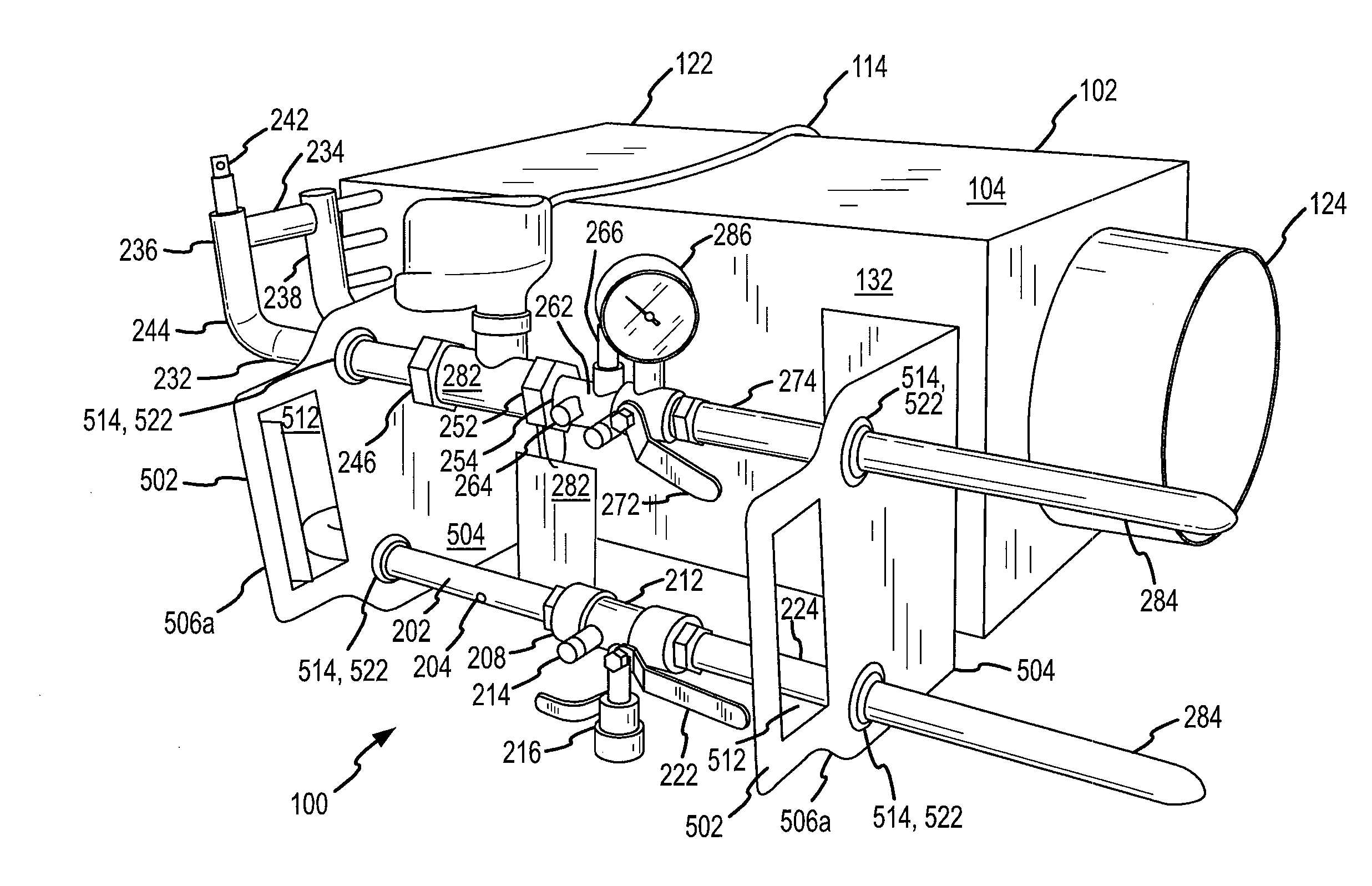
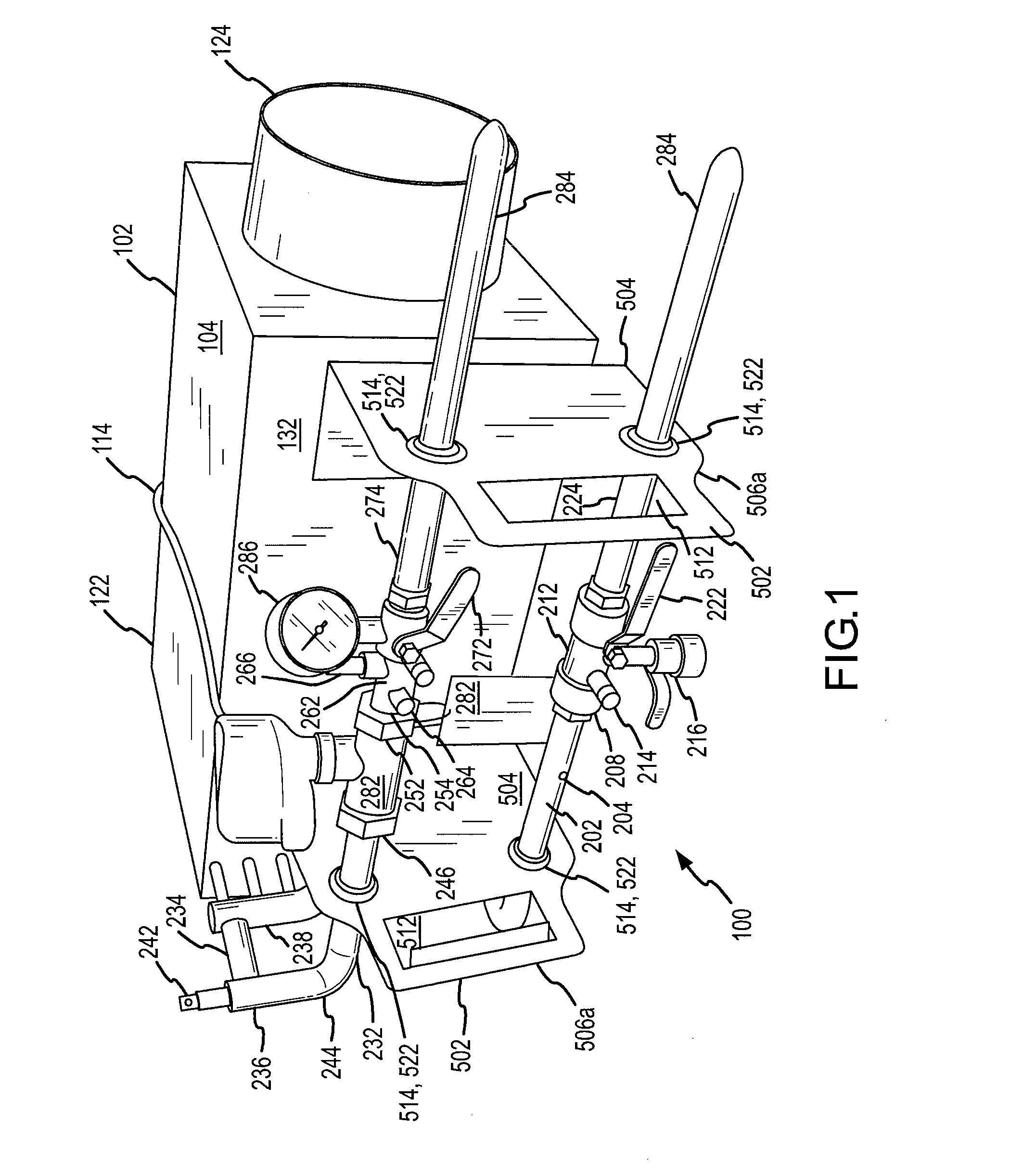
[0044] The perspective view of FIG. 1 illustrates a fully-functional HVAC terminal unit referred to by the general reference character 100. The fully-functional zone-control unit 100 depicted in FIG. 1, which illustrates one embodiment of the present invention, preferably includes a mechanical terminal unit 102 having a casing 104 visible in FIG. 1. The casing 104, which can be made from various materials of differing thicknesses, is frequently made from galvanized sheet steel material. Frequently, the casing 104 is lined with a thermal insulation material, not visible in FIG. 1, which may be chosen from various different types such as fiberglass insulation, rigid duct board fiber insulation, polyolefin, closed cell, foam insulation, etc. In some embodiments, insulation contained in zone-control unit 100 complies with an industry standard, such as a standard set by the Office of Statewide Health and Planning Department (OSHPOD).

[0045] For VAV zone-control units 100, the mechanical ...


PUM


Abstract

HVAC devices, systems, and methods include dampers for controlling the flow of air or other gasses through an HVAC duct, often while inhibiting turbulence within the duct or pressure loss within the duct. Embodiments of such dampers may employ a two-part damper arrangement. In many embodiments, flow will travel through the middle of the damper uniformly and with a laminar flow. One or more small, relatively unobtrusive sensor (optionally being wireless) can be included for controlling operation of the damper, the sensor(s) optionally measuring the distance between damper elements, sound, air flow, or the like, with such sensor(s) / damper combination inhibiting inadvertent pressure drop and turbulence in flows through the damper. The damper elements may optionally comprise airfoil cross-sections, with alternative dampers having a resilient helical configuration that can choke down flow by inducing a vortex in the flow, allowing static pressure regain to occur within the duct system.

Description

CROSS-REFERENCES TO RELATED APPLICATIONS [0001] This application claims the benefit of priority from U.S. Provisional Patent Application No. 60 / 756,037 filed Jan. 3, 2006 (Attorney Docket No. 025920-000500US). This application is related to U.S. patent application Ser. No. 11 / 429,418 filed May 5, 2006 (Attorney Docket No. 025920-000120US), which claims the benefit of U.S. Patent Application No. 60 / 678,695 filed May 6, 2005 (Attorney Docket No. 025920-000100US) and U.S. Patent Application No. 60 / 755,976 filed Jan. 3, 2006 (Attorney Docket No. 025920-00011US); and to U.S. patent application Ser. No. 11 / 180,310 filed Jul. 12, 2005 (Attorney Docket No. 025920-000210US), which is a continuation of U.S. Pat. No. 6,951,324 (Attorney Docket No. 025920-000200US); and to U.S. patent application Ser. No. 10 / 857,211 filed May 24, 2004 (Attorney Docket No. 025920-000300US); and to U.S. patent application Ser. No. 10 / 860,573 filed Jun. 2, 2004 (Attorney Docket No. 025920-000400US). This applicati...

Claims


Application Information

Patent Timeline
Patent Type & Authority Applications(United States)
IPC IPC(8): F24F7/00
CPCF24F2011/0038F24F13/1413F24F2110/30
Inventor KARAMANOS, JOHN C.
Owner KARAMANOS JOHN C
Why Eureka
Try Eureka