
High resolution imaging system

a high-resolution, imaging system technology, applied in the field of imaging systems, can solve the problems of high processing cost, high processing cost, and high cost of imaging systems, and achieve the effects of low resolution image sensor, compact and light structure, and low processing cos

Inactive Publication Date: 2007-11-15
STEREO DISPLAY
View PDF6 Cites 141 Cited by
  • Summary
  • Abstract
  • Description
  • Claims
  • Application Information

AI Technical Summary

Benefits of technology

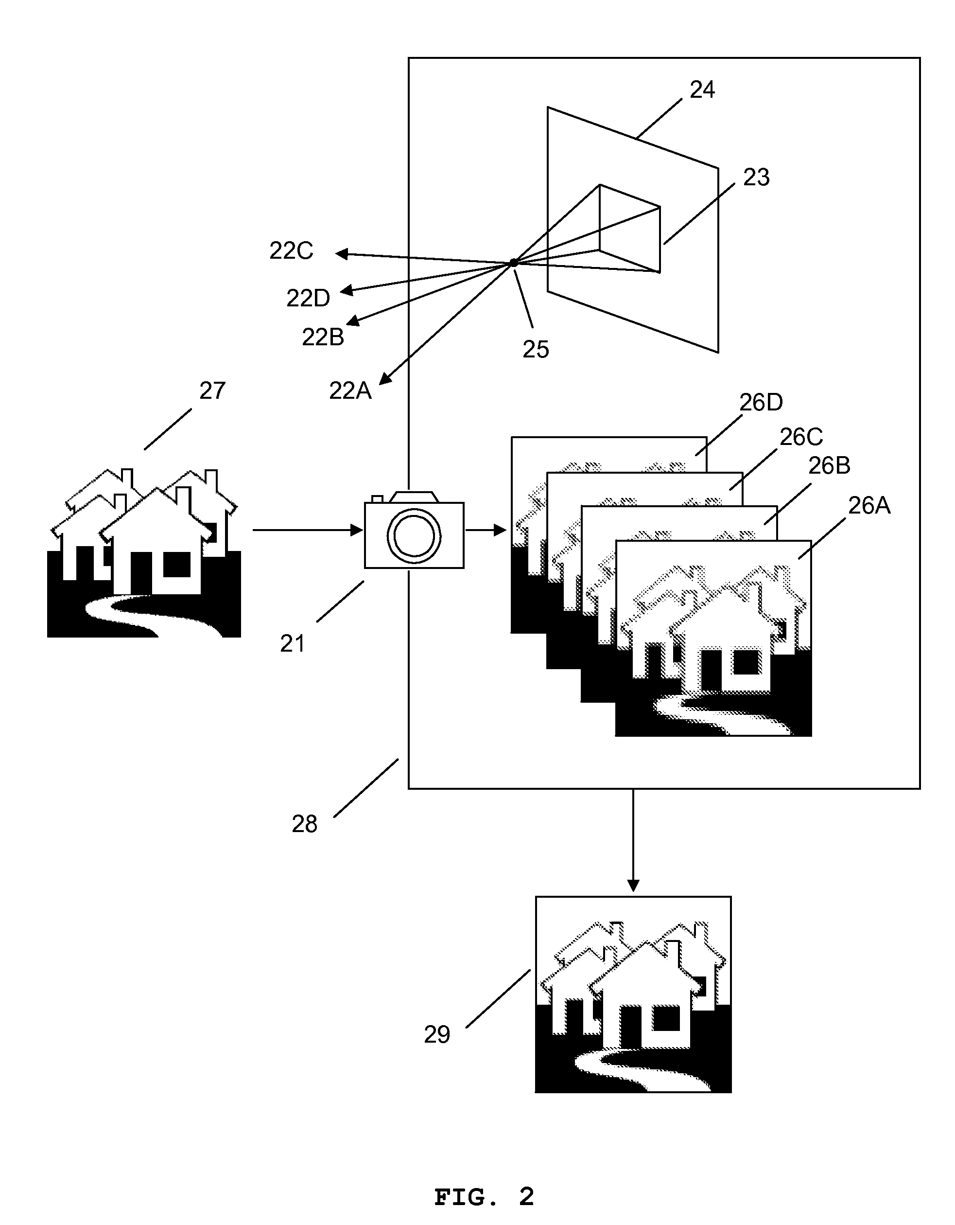
[0014] The MMAL comprising micromirrors provides a very fast response time, a large focal length variation, a high optical focusing efficiency, a simple focusing structure, low power consumption, and a low production cost because of the advantage of the mass productivity. Also, the MMAL is an adaptive optical component which compensates for the aberration of the system and changes the optical axis without macroscopic mechanical movements of lenses. The translation and / or rotation of each micromirror of the MMALs are controlled to change the focal length and the optical axis of the imaging system. Each micromirror of the MMALs is actuated by electrostatic force and / or electromagnetic force.
[0023] The imaging system of the present invention has advantages: (1) the system provides a high resolution composite image using a low resolution image sensor; (2) the system provides a wide angle of view; (3) the system has a compact and light structure because the size of the image sensor is small and there is no macroscopic mechanical movements of lenses; (4) the system is inexpensive because the low resolution image sensor and the MMAL are inexpensive and the macroscopic mechanical movements of lenses are not necessary; (5) the system has a compact zoom system; (6) the system has a very high zooming speed; (7) the system has a large variation of magnification; (8) the system has a high optical efficiency; (9) the system provides an auto focusing function; (10) the system compensates for the aberration of the system; and (11) the system requires small power consumption because the number of pixels of the image sensor is small and the MMAL is actuated by electrostatic force.

Problems solved by technology

Such an imaging system tends to become bulky and heavy as well as cost more.
Increasing image sensor resolution can cause other problems including more processing time, more power consumption, and higher cost.
The device yields complicated structures while providing a fixed resolution unless shutter means and the compound eye lens are replaced.
The direction control unit of Ishida moves a whole housing containing an optical unit and an image sensor, resulting in a complicated driving mechanism.
The improvement of resolution is limited by the shape of the optical wedge.
Also, the actuator moving the wedge assembly uses a macroscopic servo mechanism which can induce vibration and time delay causing deterioration of the image quality.
Conventional imaging system does not provide optical axis change unless it adds bulky structure and cost.

Method used


Image

  • High resolution imaging system
  • High resolution imaging system
  • High resolution imaging system

Examples


Embodiment Construction

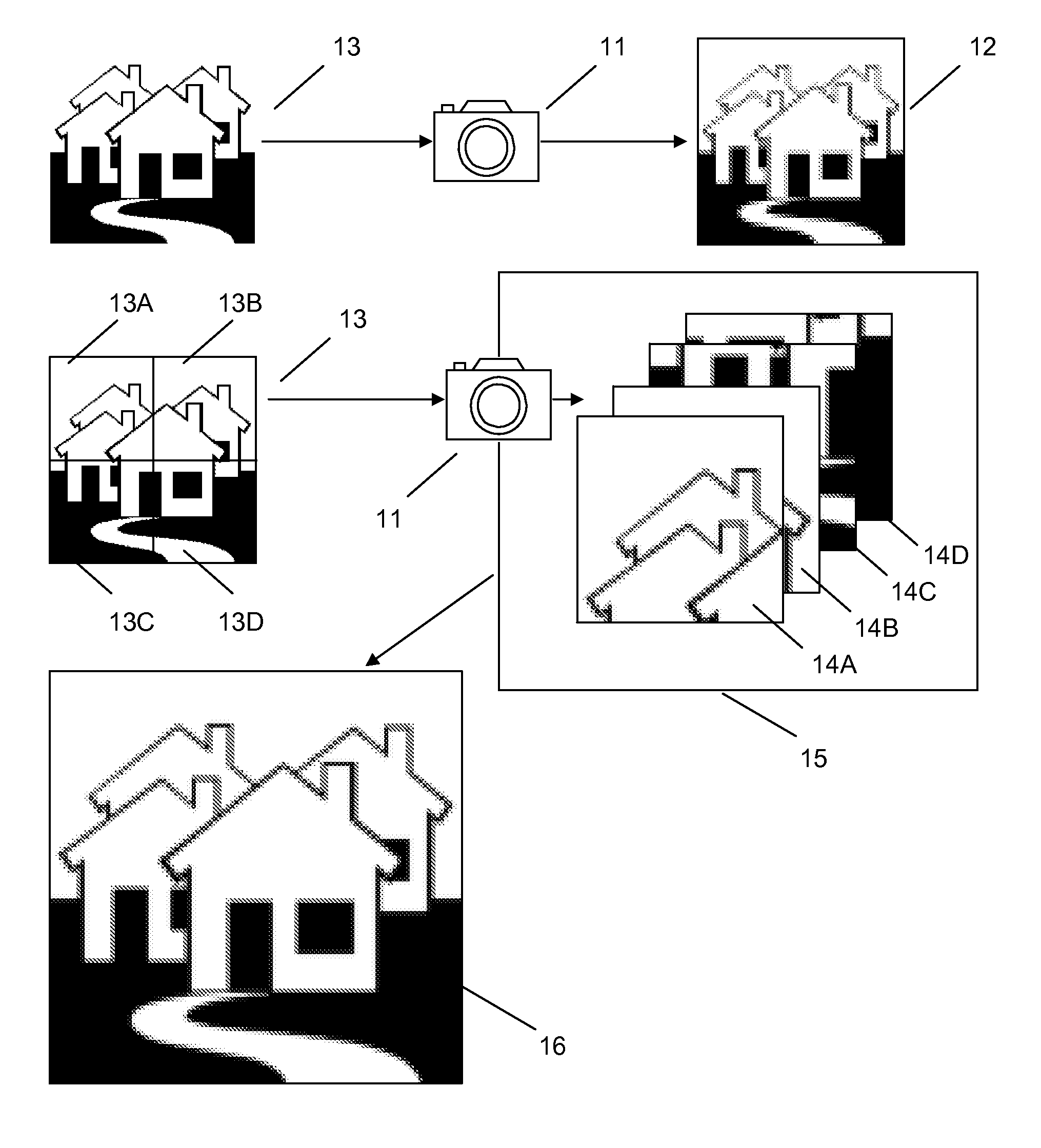
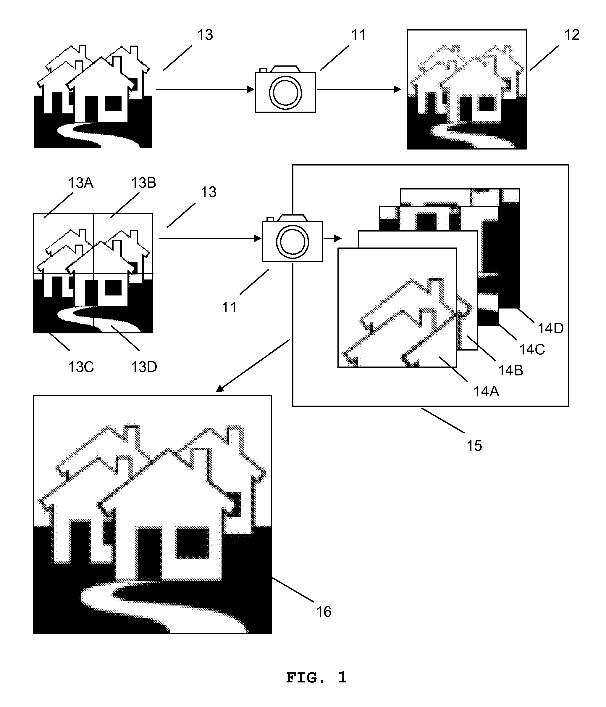
[0038]FIG. 1 shows an illustrative exemplary imaging system 11 having a low resolution image sensor, which improves image resolution by a mosaic method. A user chooses a desired image resolution; preferably, integer times of image sensor resolution although it is not necessary. The desired image resolution determines other variables including the amount of magnification and pointing directions of an optical axis. Values of variables can be calculated in real-time in an arithmetic unit or calculated in advance for predetermined resolutions and stored in the arithmetic unit. The highest feasible composite image resolution depends on the zoom range and optical axis variation range of the imaging system. In the normal operation of the imaging system 11, the image 12 of an object 13 has the same resolution as that of the image sensor. The user may need a higher resolution image because the image 12 does not show enough details of the object 13. When the higher resolution image is require...


PUM


Abstract

The present invention provides an imaging system generating a high resolution image using low resolution images taken by a low resolution image sensor. Also, the imaging system generates a wide angle of view image. Enhancement of resolution and enlargement of angle of view are accomplished by optical axis change, utilizing one or more micromirror array lenses without macroscopic mechanical movements of lenses. The imaging system also provides zoom and auto focusing functions using micromirror array lenses.

Description

FIELD OF INVENTION [0001] The present invention relates to an imaging system providing high resolution images with a low resolution image sensor.BACKGROUND OF THE INVENTION [0002] A high resolution imaging system with compact size, light weight, high speed, low power consumption, and low cost is in high demand. Resolution can be defined in many ways. In this disclosure, image resolution means spatial image resolution which is defined as the number of picture elements used to represent an image captured with a given field of view and depends on mainly image sensor resolution. Image sensor resolution is determined by various factors including the size of the image sensor and the pixel size of the image sensor. To provide high image sensor resolution for a given pixel size, the size of the image sensor needs to be increased, which causes the aperture and the focal length of an imaging system to be increased. Such an imaging system tends to become bulky and heavy as well as cost more. T...

Claims


Application Information

Patent Timeline
IPC IPC(8): H04N5/225
CPCG02B26/0825H04N5/2254H04N5/2259H04N5/23296H04N5/23232H04N5/23238H04N5/23212H04N23/58H04N23/951H04N23/698H04N23/69
Inventor BAEK, SANG HYUNECHO, GYOUNG ILSEO, CHEONG SOO
Owner STEREO DISPLAY
Learn More