MIMO wireless data communication system, MIMO wireless data communication method and MIMO wireless data communication apparatus

a wireless data communication and wireless data technology, applied in the field of wireless data communication systems, mimo wireless data communication methods and mimo wireless data communication apparatus, can solve problems such as inability to solve, and achieve the effect of increasing the number of modulation levels and large communication capacity

Inactive Publication Date: 2007-11-15
HITACHI LTD
View PDF5 Cites 10 Cited by
  • Summary
  • Abstract
  • Description
  • Claims
  • Application Information

AI Technical Summary

Benefits of technology

[0026]The present invention realizes a large communication capacity without increasing the number of levels of modulation even in a communication environment capable of achieving a high SNR, in a MIMO wireless communication system for eigenmode transmission.

Problems solved by technology

However, this method deals with only multicarrier transmission such as OFDM.
Further, this method cannot solve the problem that the number of levels of modulation cannot be made large in the first eigenmode which inherently obtains a high effective SNR.

Method used


Image

  • MIMO wireless data communication system, MIMO wireless data communication method and MIMO wireless data communication apparatus
  • MIMO wireless data communication system, MIMO wireless data communication method and MIMO wireless data communication apparatus
  • MIMO wireless data communication system, MIMO wireless data communication method and MIMO wireless data communication apparatus

Examples


first embodiment

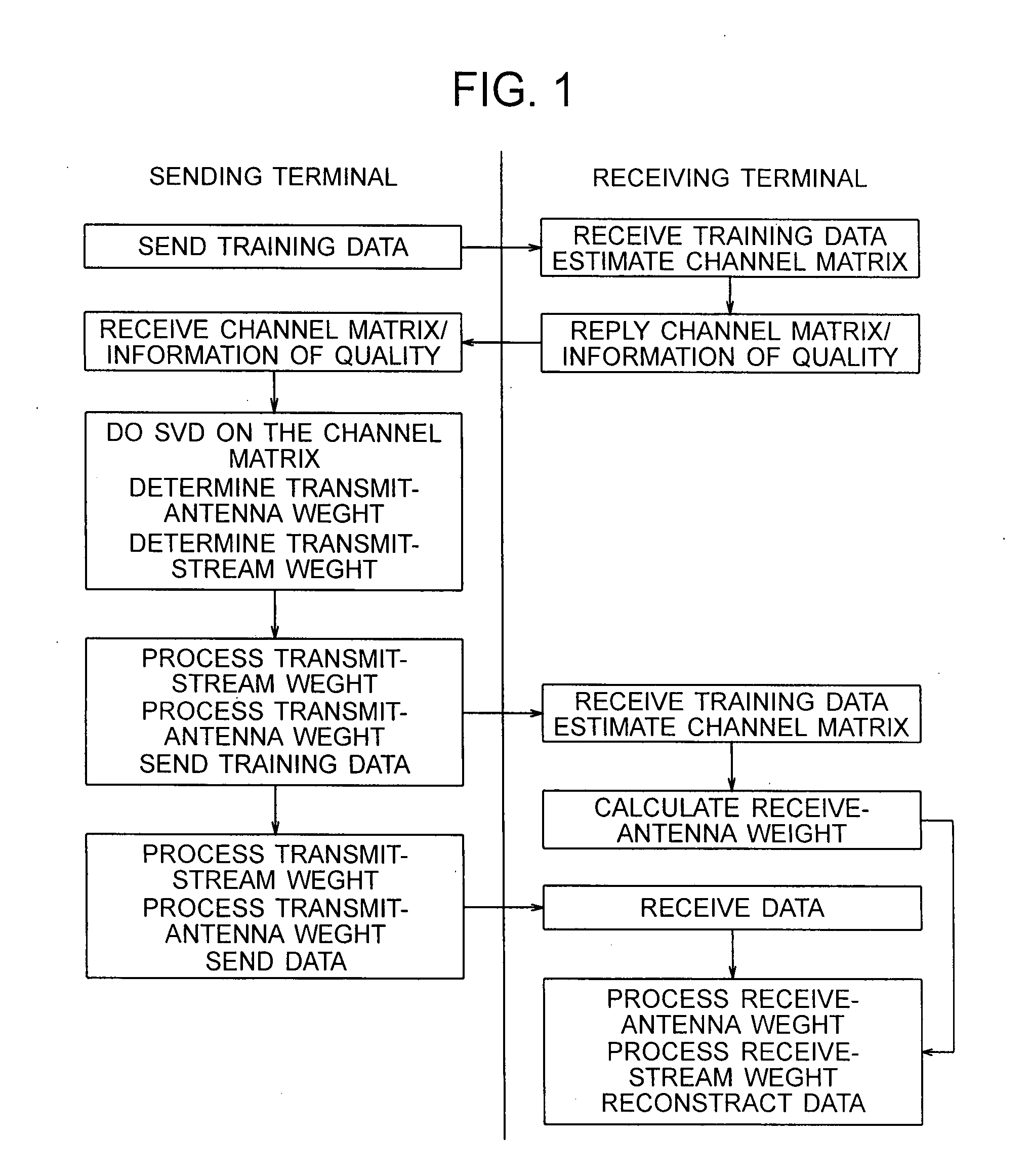
[0047]FIG. 1 shows a sequence of a MIMO wireless communication method according to the first embodiment of the present invention. In FIG. 1, although data is transmitted from a transmission terminal to a reception terminal, both the terminals have the function of both transmission and reception so that control information and the like can be transferred therebetween.

[0048]First, the transmission terminal transmits training data, and the reception terminal receives the training data. Training data is already known signals defined by specifications or the like, and the channel matrix can be estimated by monitoring a change in the amplitude and phase of the known signals. Next, the reception terminal returns the channel matrix obtained through estimation and communication quality information to the transmission terminal. SNR or RSSI may be used as the communication quality information. The transmission terminal receives the returned channel matrix and communication quality information....

second embodiment

[0050]FIG. 5 shows a sequence of a MIMO wireless communication method according to the second embodiment of the present invention. Similar to the first embodiment, in FIG. 5, although data is transmitted from a transmission terminal to a reception terminal, both the terminals have the function of both transmission and reception so that control information and the like can be transferred therebetween.

[0051]First, the transmission terminal transmits training data, and the reception terminal receives the training data. Training data is already known signals defined by specifications or the like, and the channel matrix can be estimated by monitoring a change in the amplitude and phase of the known signals. Next, the reception terminal makes the channel matrix obtained through estimation be subjected to singular value decomposition to obtain the transmission antenna weight for the eigenmode transmission method and singular values of each eigenmode. A communication quality indicator of ea...

third embodiment

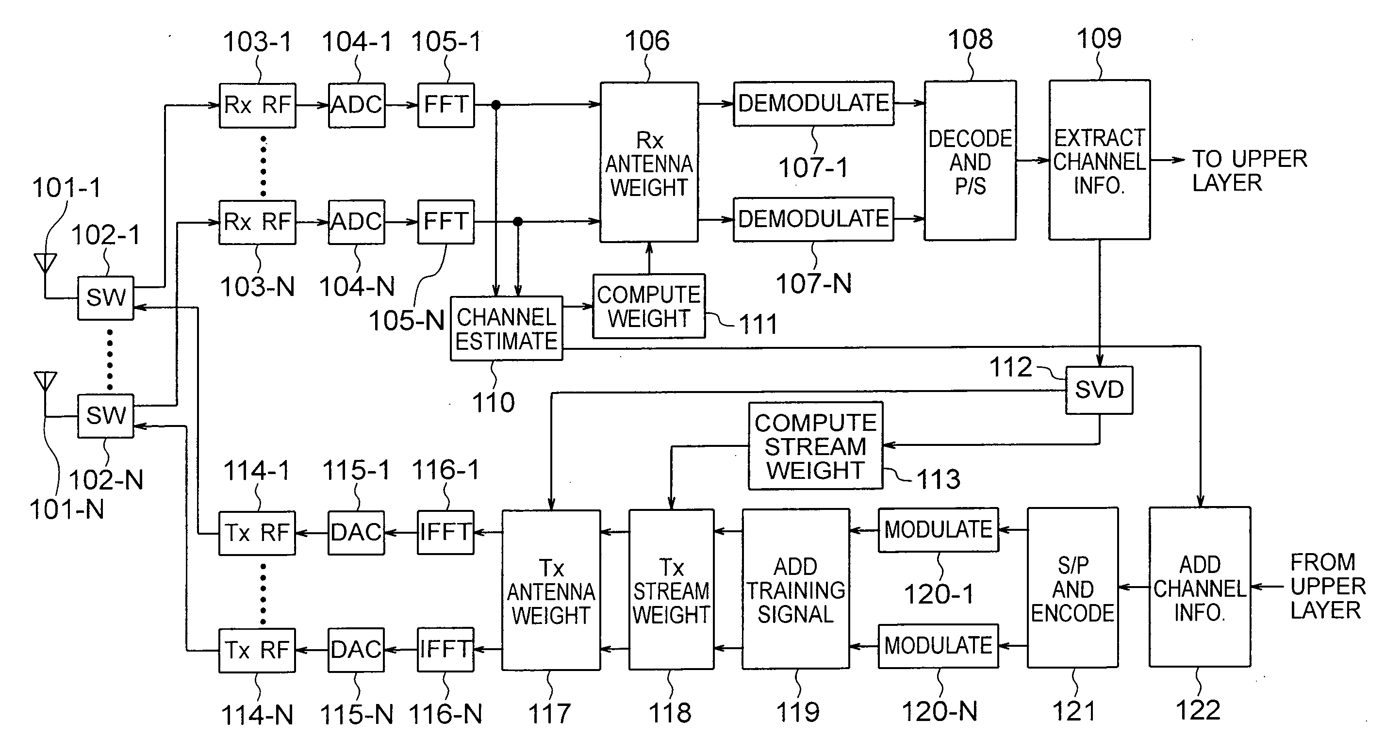
[0053]FIG. 9 is a functional block diagram of a wireless communication apparatus for communications by the MIMO wireless communication method of the present invention, according to the third embodiment.

[0054]The wireless communication apparatus shown in FIG. 9 has N antennas 101-1 to 101-N and are connected to switches 102-1 to 102-N, respectively. The switch 102 interconnects a transmission circuit and an antenna for transmission by the wireless communication apparatus, and interconnects a reception circuit and the antenna for reception by the wireless communication apparatus. The switch 102 is required in a system adopting a time division duplex (TDD) method often used by wireless LAN, and is equipped with a filter called a duplexer in a system adopting a frequency division duplex (FDD) method often used by mobile phones.

[0055]For reception, the switch 102 interconnects the antenna 101 and a reception analog RF circuit 103. The reception analog RF circuit performs down-conversion ...


PUM


Abstract

In a MIMO wireless communication system, the transformation process synthesizes the eigenmodes having a large singular value (i.e. a high effective SNR) and the eigenmodes having a small singular value (i.e. a low effective SNR). Thereby, the former eigenmodes are converted into modes having suppressed effective SNR which do not require a large number of levels of modulation, and the latter eigenmodes are converted into modes having increased effective SNR instead. In a MIMO wireless communication system for eigenmode transmission, a large communication capacity is realized without increasing the number of levels of modulation even in a communication environment capable of achieving a high SNR.

Description

CLAIM OF PRIORITY[0001]The present application claims priority from Japanese application JP2006-134691 filed on May 15, 2006, the content of which is hereby incorporated by reference into this application.BACKGROUND OF THE INVENTION[0002]1. Field of the Invention[0003]The present invention relates to a multiple-input multiple-output (MIMO) wireless communication method for communications between a sending or transmission terminal having a plurality of antennas and a receiving or reception terminal having a plurality of antennas and a MIMO wireless communication apparatus for communications by the MIMO wireless communication method. More particularly, the present invention relates to a MIMO wireless communication method and apparatus for communications at a high transmission rate if a signal-to-noise (SNR) ratio is high for an eigenmode transmission method which is one type of the MIMO communication method.[0004]2. Description of the Related Art[0005]A communication method has advanc...

Claims


Application Information

Patent Timeline
Patent Type & Authority Applications(United States)
IPC IPC(8): H04L1/02H04J99/00H04W16/28H04W28/00H04W92/10
CPCH04B7/0854H04B7/0615
Inventor HAYASE, SHIGENORISHIDA, MASAAKIYAMAMOTO, KEISUKE
Owner HITACHI LTD
Why Eureka
Try Eureka