Dental implant and method for making and installing same

a dental implant and implant technology, applied in dental prosthesis, dental surgery, medical science, etc., can solve the problem of more healing time and other problems, and achieve the effect of promoting bone growth and reducing micro-movement of implants

Inactive Publication Date: 2007-11-15
MOUNT K TIM
View PDF27 Cites 81 Cited by
  • Summary
  • Abstract
  • Description
  • Claims
  • Application Information

AI Technical Summary

Benefits of technology

[0032] The software automatically creates a random pattern of chevron retention fins on the root portion of the implant. These chevrons act somewhat like threads on conventional implants but do not create a spiral threading motion when placing the implant. They allow for bone compression as the implant seats but are one directional and will not allow the implant to come back out of the socket. This eliminates micro-movement of the implant at the time of placement and thus encourages bone growth to the titanium alloy surface treated root portion of the implant.
[0033] The dentist can rotate the three dimensional image of the proposed one-piece combination implant and abutment on the equipment monitor to check all aspects of the one-piece unit and can override the automatic computer design by eliminating a chevron or making any modification that he feels is an improvement on the computer solution. Once the dentist is satisfied with the design that is shown on the monitor, the “mill” command is selected and manufacturing of the milled implant is completed within approximately fifteen minutes.
[0034] The milled implant may not have a root portion exactly like the extracted tooth but it will be essentially the same and will be modified enough to allow it to seat to place in the p...

Problems solved by technology

Conversely, if the bone quality wa...

Method used


Image

  • Dental implant and method for making and installing same
  • Dental implant and method for making and installing same
  • Dental implant and method for making and installing same

Examples


Embodiment Construction

The Invention

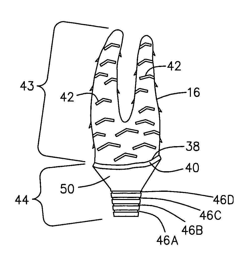
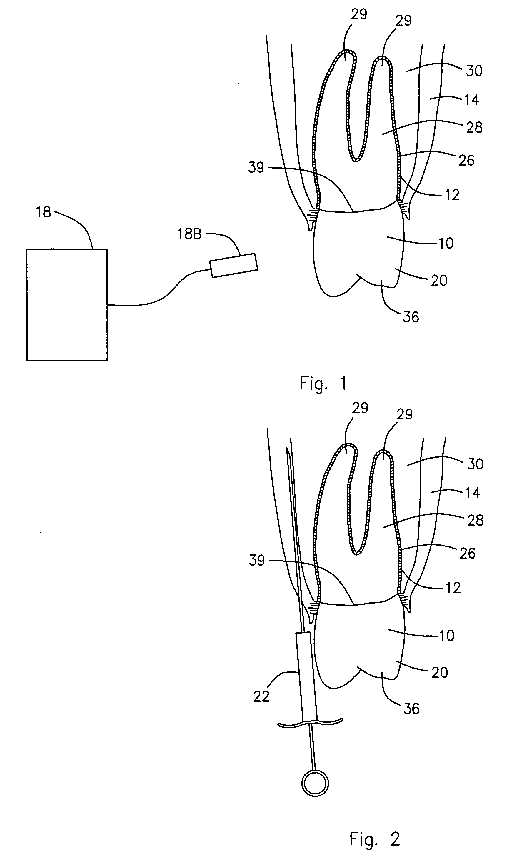
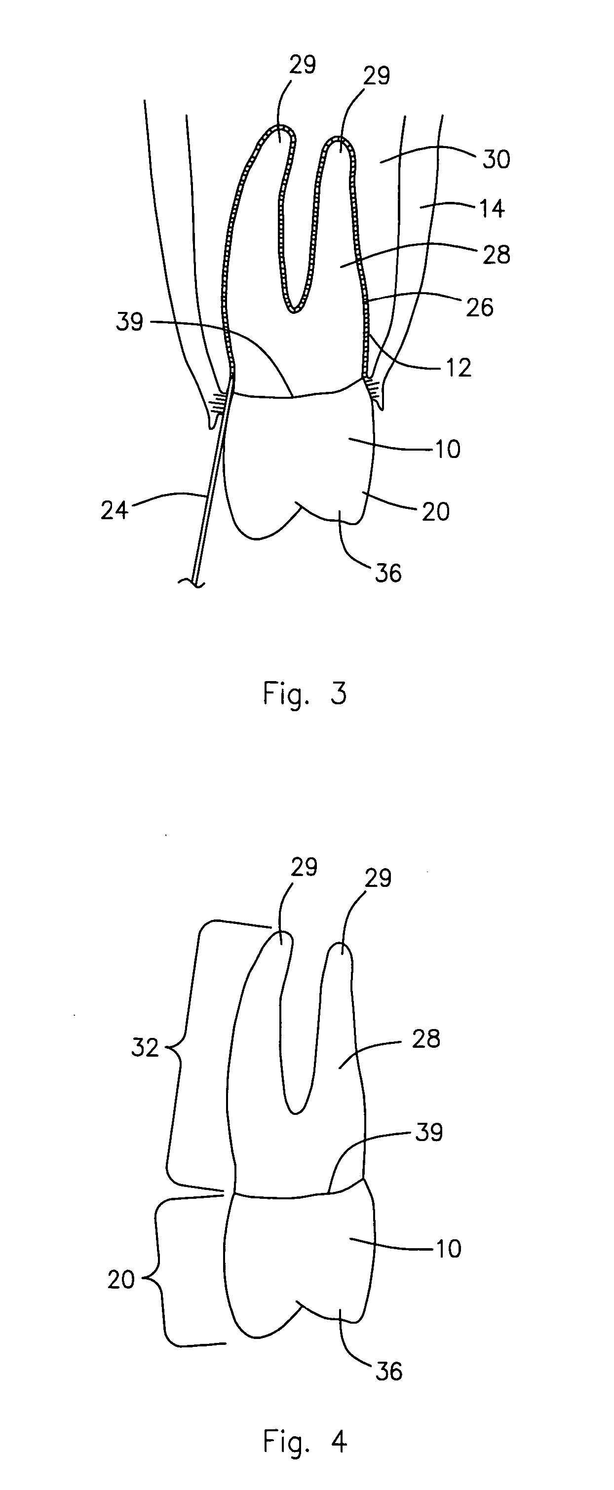
[0061] Referring now to the drawings and initially to FIG. 1, there is shown a tooth 10 that is about to be extracted from a tooth socket 12 in a patient's mouth 14 and, as shown in FIG. 10, replaced with an implant 16 according to a preferred embodiment of the present invention. The present invention is a dental implant 16 and method for making and installing that dental implant 16 into a patient's mouth 14.

[0062] This invention normally involves replacement of a tooth 10 with an implant 16 immediately after the tooth 10 is extracted. The process employs prior technology such as the CEREC CAD / CAM equipment that is illustrated in FIGS. 1, 5, and 6A. This CAD / CAM equipment 18 provides the ability to acquire three dimensional images of the tooth 10 via a camera 18B that is part of the equipment 18 and the capability to machine a titanium implant 16. However, this invention can also be employed to replace a tooth or teeth that have been extracted much earlier, or alt...


PUM


Abstract

A method for making a dental implant by obtaining images of the tooth pre-atraumatic tooth extraction and post extraction and using those images to computer generate and mill a titanium replacement implant employing CAD/CAM equipment. The implant includes a scalloped neck interface similar to the replaced tooth's scalloped cementoenamel junction, a polished neck area between a root portion and a crown portion, and the numeral for the tooth number imprinted on the implant's facial surface. Chevron retention fins are provided on the root portion for engaging the bone of the tooth socket or osteotomy when the implant is tapped into position. Retention grooves are provided on the crown portion to which a provisional crown is cemented slightly out of occlusion at the time the implant is placed. The provisional crown will be replaced with a permanent crown after osteointegration of the implant has occurred.

Description

BACKGROUND OF THE INVENTION [0001] 1. Field of the Invention [0002] The present invention relates to a method for making a dental implant by obtaining images of the tooth pre-atraumatic tooth extraction and post extraction and using those images to computer generate and mill a titanium alloy replacement implant employing CAD / CAM equipment. [0003] 2. Description of the Related Art [0004] Computer aided design and computer aided machining (CAD / CAM) have been employed in producing dental restorations and implant abutments. Patents already exist and the technology has been in use for a number of years for employing a three dimensional optical camera to capture an optical impression (image acquisition) of a subject tooth as well as a tooth on each side of the target tooth. [0005] Sirona Dental Company produces the CEREC 3D, which is a CAD / CAM unit that is used at patient chairside. The unit makes an optical impression, or acquisition, of a prepared tooth and can mill a precise ceramic re...

Claims


Application Information

Patent Timeline
IPC IPC(8): A61C8/00
CPCA61C8/00A61C13/0004A61C13/0003A61C8/0043G16H20/40
Inventor MOUNT, K. TIM
Owner MOUNT K TIM
Why Eureka
Try Eureka