
Method and system for determining process parameters

a technology of process parameters and methods, applied in the field of methods and systems for determining process parameters, can solve the problems of unsatisfactory temperature distribution of products, and achieve the effect of speeding up analysis and facilitating analysis

Inactive Publication Date: 2007-11-15
JOHN BEAN TECH AB
View PDF34 Cites 22 Cited by
  • Summary
  • Abstract
  • Description
  • Claims
  • Application Information

AI Technical Summary

Benefits of technology

[0017] The analysis of the temperature or temperature distribution may be performed on site or at a different centralised location. One advantage with using a centralised location is that temperature measurements from several treatment units at completely different locations may be used as input in the determination of appropriate process parameters. It is also easier to provide expert operators supervising or guiding the analysis and determination of appropriate process parameters. It is also easier to update the equipment (hardware and software) used to perform the analysis and determination of appropriate process parameters.
[0022] The method may further comprise receiving data representing the temperature distribution or temperature of a plurality of products treated in a plurality of treatment units and based on said received data determining said set of process parameters for a temperature treatment in a treatment unit. By analysing data from several treatment units it will e.g. be possible to detect if a specific treatment unit has a non-typical response to a change in process parameters thereby making it possible to investigate treatment units with too low yield. It will also be possible to determine a set of process parameters that will provide a robust treatment process that can be performed on different treatment units even if they run under slightly different circumstances. The set of process parameters determined from data from several treatment units may also be provided to other treatment units than those that has provided the data.
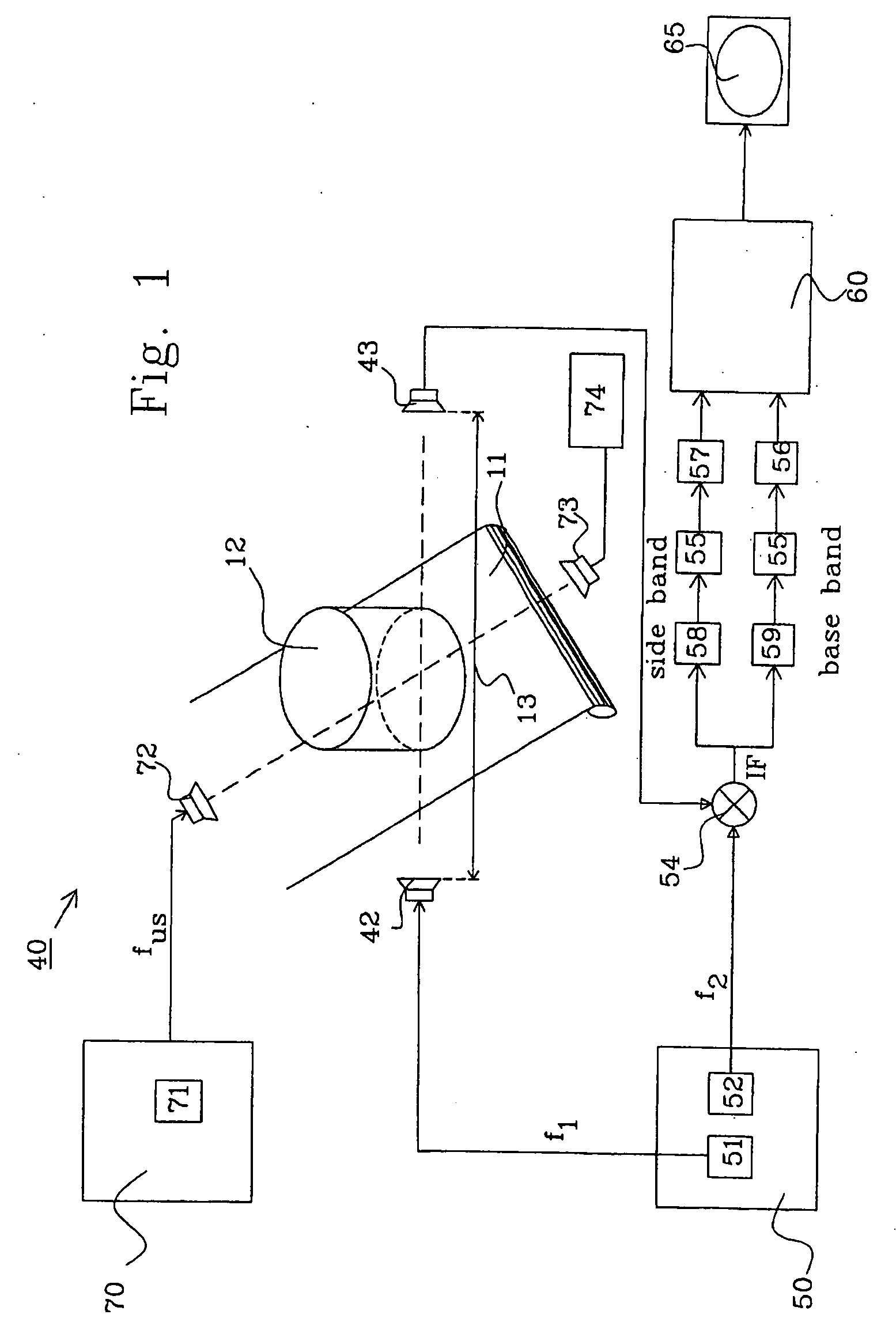
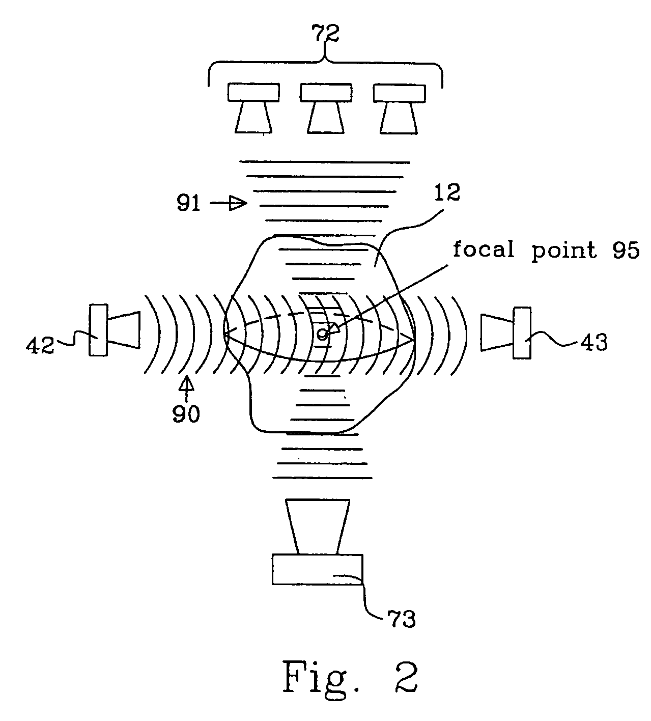
[0024] The interference phenomenon makes it possible to determine the point where the two signals have interfered and from where the dielectric constant has given rise to change of the received the electromagnetic signal compared to the transmitted electromagnetic signal. The electromagnetic (e.g. microwave) signal exhibits damping and phase delay by travelling through the product leaving the frequency unchanged. In those volumes of the product under test where the interference occurs (e.g. where the ultrasound wave creates a density displacement) a part of the electromagnetic (e.g. microwave) signal is shifted in frequency and upper and lower sidebands are created. By receiving these frequency shifted signals and studying e.g. the damping and phase delay it is possible to get information concerning the dielectric constant between the point of interference and the point of receipt of the signal. By creating a interference patter in e.g. a layer-by-layer fashion it will be possible to simplify and to speed up the analysis considerably. This may e.g. be done by measuring the dielectric constant initially in an outermost surface layer by creating an interference close to the surface and then measure the signal as it passes through this layer. This will give information concerning the dielectric constant in this layer and this will then be a known parameter when analysing the response from an interference in a second outermost layer giving rise to a interfered signal travelling through the second (unknown) outermost layer and the outermost (known) layer. Other kinds of controlled interference sweeps or systems may also be used. The actual sweep of the interference may be optimised considering practical aspects as long as the information may draw benefit from the fact that the known origin of the interfered signal facilitates the analysis. It is also contemplated that the analysis may be performed in the fly, i.e. during the sweep of the interference but it is also contemplated that the analysis is performed at a later time after the complete data set has been collected. If the practically feasible sweep pattern correlates with a convenient analysis set-up it is possible to determine the temperature in the fly (and thereby to end the measurement when enough information has been received). With a double interference system it will e.g. also be possible to provide two virtual probes within a product. This is discussed in more detail in the detailed description.
[0036] The second transmitter may adapted subject said product to a second signal capable of providing a, in time and position, local change of the density of said product and thereby locally, in time and position, influencing the dielectric constant distribution.

Problems solved by technology

A similar consideration may also be taken into account if the temperature measurement is performed after the treatment and it is found that the temperature distribution within the product is unsatisfactory in that the coldest portion is too close to a minimum temperature, while the surface is heated to a satisfactory level.

Method used


Image

  • Method and system for determining process parameters
  • Method and system for determining process parameters
  • Method and system for determining process parameters

Examples


first embodiment

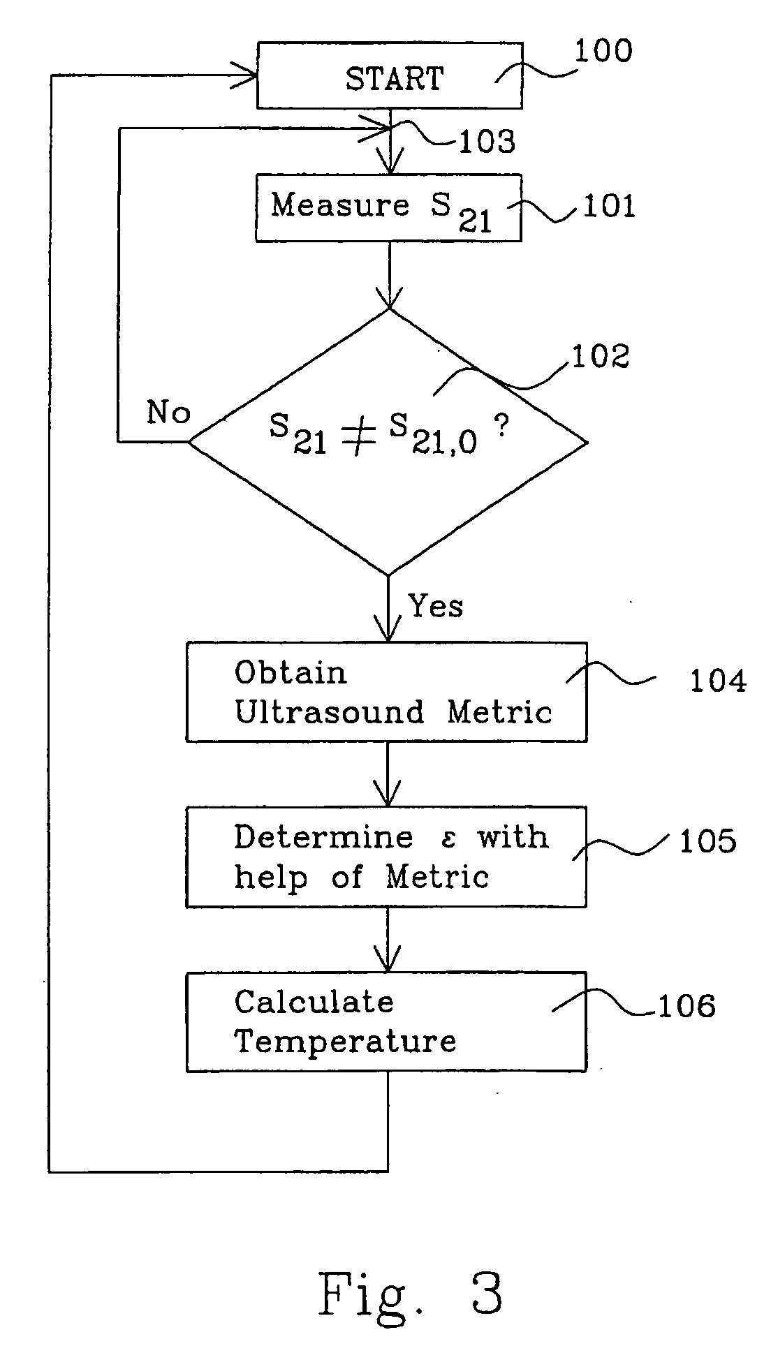
[0098]FIG. 5a shows a first embodiment for determining the dielectric function in an object, such as a food product, to determine a physical property in the object, such as internal temperature without physically probing the object, during preparation of the object.

[0099] The flow starts in step 110, where a point in the object is selected. It is advantageous to select a point that has been used during the process of obtaining the ultrasound metric. The selected point corresponds to point 3 in equations 1-17.

[0100] The ultrasound radiation is thereafter focused on this point in step 111 and in step 112, the S-parameters S31 and S23 are measured, as described in more detail in connection with FIG. 6.

[0101] In step 113, a decision is made whether another point should be selected or not. If another point should be selected the flow is fed back to step 110, where a new point is selected before steps 111 and 112 are repeated. If not, the flow continues to step 114 where the matrix with...

second embodiment

[0103]FIG. 5b shows a second embodiment for determining the dielectric function in an object, such as a food product, to determine a physical property between two locations in the object, such as material properties, e.g. the presence of a brain tumour, without physically probing the object.

[0104] The flow starts in step 210, where a pair of points in the object is selected. It is advantageous to select points that have been used during the process of obtaining the ultrasound metric. The selected points correspond to point 3 and 4 in equations 1-17.

[0105] The ultrasound radiation is thereafter focused on both points in step 211 and in step 212, the S-parameters S31, S23, S41, S24, S4′1, S24′, S3′1 and S23′ are measured, as described in more detail in connection with FIG. 7.

[0106] The S-parameter S43, i.e. the damping between the selected points, is calculated in step 213. Point 3 acts as a virtual transmitter and point 4 functions as a virtual receiver in this embodiment.

[0107] T...


PUM


Abstract

The present invention relates to a method and a system for determining a set of process parameters of a treatment unit in which unit a product is subjected to a temperature treatment, the method comprising: subjecting a product to an electromagnetic signal before, during and / or after a temperature treatment, wherein said electromagnetic signal is adapted to interact with said product dependent upon the dielectric constant distribution of said product, receiving an electromagnetic signal which has interacted with said product, analysing the received electromagnetic signal in comparison with the transmitted electromagnetic signal and thereby determining a response being dependent upon the dielectric constant distribution of said product and based thereupon determine the temperature (distribution) or water content of the product, and analysing said temperature distribution or temperature of the product or products and based thereupon determining a set of process parameters for a temperature treatment in a treatment unit.

Description

FIELD OF INVENTION [0001] The invention relates to a method of determining a set of process parameters of a treatment unit in which unit a product is subjected to a temperature treatment. [0002] The invention further relates to a system for determining a set of process parameters of a temperature treatment unit. TECHNICAL BACKGROUND [0003] There exist a number of different kinds of methods for measuring the temperature of a product. [0004] U.S. Pat. No. 4,499,357 discloses an electronically controlled cooking apparatus in which an article to be heated is heated for cooking through measurement of temperature thereof by an infrared sensor. The infrared sensor is arranged to detect surface temperature of the article to be heated in electronically controlled cooking apparatuses of this kind. A problem with heating of food products is that the surface often reaches a high temperature fairly quickly whereas it often takes considerable time before the inside of the product reaches the requ...

Claims


Application Information

Patent Timeline
Patent Type & Authority Applications(United States)
IPC IPC(8): A61B5/05A23L5/10
CPCH05B6/062
Inventor PAHLSSON, STENGUNAWARDENA, RAMESH M.
Owner JOHN BEAN TECH AB
Learn More