Atherectomy system having a variably exposed cutter

a technology of atherectomy and cutter, which is applied in the field of improved atherectomy system, can solve the problems of safety and embolization, excessive debris being sent distally, and time-consuming to set up the rotablator® system, and achieve the effects of improving cutting efficiency, improving safety and reducing the risk of infection

Active Publication Date: 2007-11-15
BOSTON SCI LTD
View PDF53 Cites 75 Cited by
  • Summary
  • Abstract
  • Description
  • Claims
  • Application Information

AI Technical Summary

Benefits of technology

[0012]2. The positionable tip at the distal end of the catheter tube can be deployably deformed about a hinge mechanism to form an angle with the immediate adjacent portion of the catheter tube just proximal to the hinge mechanism upon activation of a deployment wire extending internally nearly the length of the small lumen of the catheter tube and freely exiting the catheter tube in close proximity to the positionable tip. The angularly deployed positionable tip shape exposes the cutter and makes the cutter available to negotiate the atheromatous material. The degree to which the positionable tip is angled with respect to the immediate adjacent proximal portion of the catheter tube just proximal to the hinge mechanism affects the depth of cut.
[0013]3. The combination of the positionally fixed cutter with high velocity fluid jets removes the need for moving parts at the distal catheter tube positionable tip other than the deployment wire which is employed to angularly configure the positionable tip. This combination incorporating the use of a cutter with high velocity fluid jets provides better cutting. The cutter can generate focal mechanical forces at the cutting edge that are much greater than those generated by the high velocity fluid jets. However, the high velocity fluid jets are continually cleaning the cutter by macerating and evacuating debris. Otherwise, the cutter would plug up with debris and become ineffective. Thus, the complementary action of the cutter and high velocity fluid jets yields a mechanically simple yet efficacious cutting solution.
[0014]4. The combination of the high velocity fluid jets with the cutter also affords another advantage. The safety of the system can be modified in three ways. The more severe the depth of cut (the greater the angulation of the positionable tip), the more potentially injurious the catheter tube may be to the native vessel wall. Accordingly, the safety of the system can be affected by observing and reducing the deployment angle of the positionable tip. Similarly, the sharpness of the outward edge of the cutter will affect both the efficacy of the cutting and the safety of the catheter. A sharper external edge of the cutter has greater potential for injury to the vessel wall. Finally, the recirculating fluid can act as a lubricating layer to deflect the healthy pliable vessel, yet it would not deflect thickened hard plaque away from the cutter.
[0016]6. The positionable tip of the catheter has a nitinol support structure functioning as a hinge mechanism. The mechanical properties of nitinol ensure that the positionable catheter tip can be bent or rotated about the hinge mechanism while maintaining appropriate mechanical support of the distal end of the catheter; i.e, the positionable tip. The positionable tip is formed of a tubular uncoated nitinol section with an appropriately shaped notch or gap placed in the center portion of the tubular uncoated nitinol section. The notch is essential and relevant in the formation and operation of the hinge mechanism. The deployment wire runs for the most part along the small lumen of the catheter tube and then exits the tubular uncoated nitinol section and extends externally to the most distal part of the positionable tip and attaches thereto. When actuated in a proximal direction, the deployment wire exerts force on the distal end section of the positionable tip to cause it to bend or deform in a reliable fashion about the hinge mechanism, thus exposing the cutter. Furthermore, if the deployment wire is relaxed, the superelastic properties of the nitinol return the positionable tip to its straight configuration. The notch and hinge mechanism operate to reveal the cutter. Hence, the notch and hinge mechanism allow useable revealing of the fixed cutter and also accomplish elastic recovery of the positionable tip. Alternatively, a PEBAX® catheter body can be a separate structure affixed to the end of the nitinol hinge.

Problems solved by technology

Secondly, the Rotablator® system has been characterized as time intensive to set up.
The issues with the device involve vessel safety and embolization.
Secondly, the device directs the skived material (it whittles out strips of the plaque versus sanding it away) toward the tip of the catheter.
Once the tip is full of these skived strips, there have been reported instances of excess debris being sent distally (embolization).
The Simpson catheter would be difficult to operate in long stretches of diseased vessel.
Furthermore, both devices suffer from not encouraging material to be removed.
However, the high velocity fluid jets will not distinguish between diseased tissue and the healthy vessel wall.

Method used


Image

  • Atherectomy system having a variably exposed cutter
  • Atherectomy system having a variably exposed cutter
  • Atherectomy system having a variably exposed cutter

Examples


Embodiment Construction

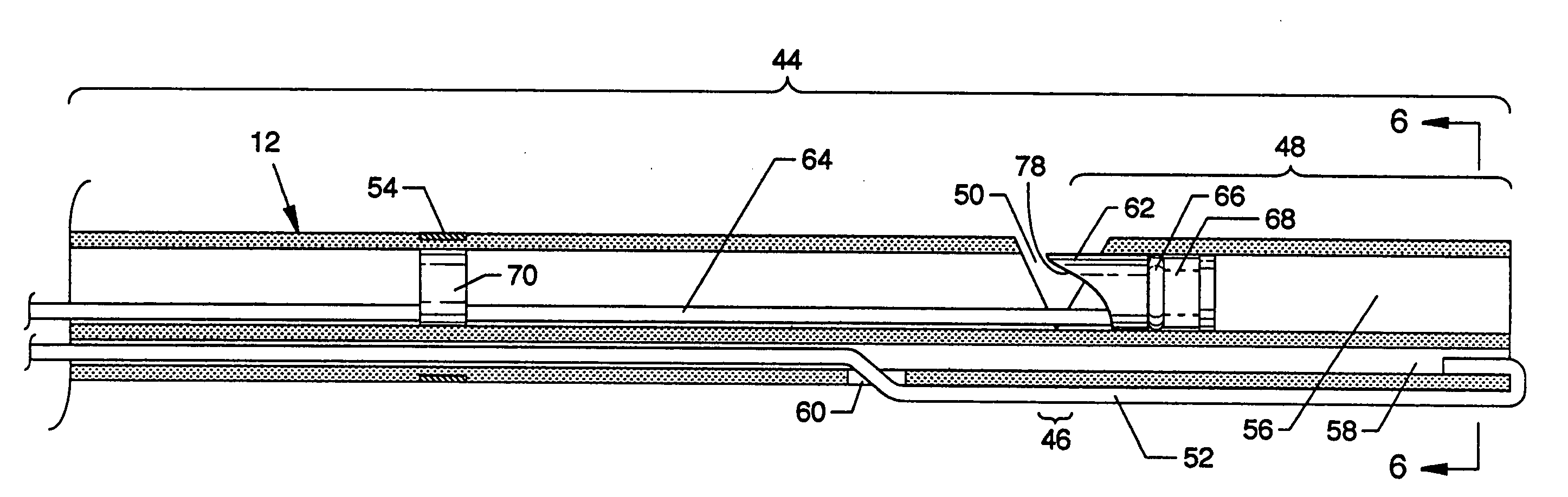
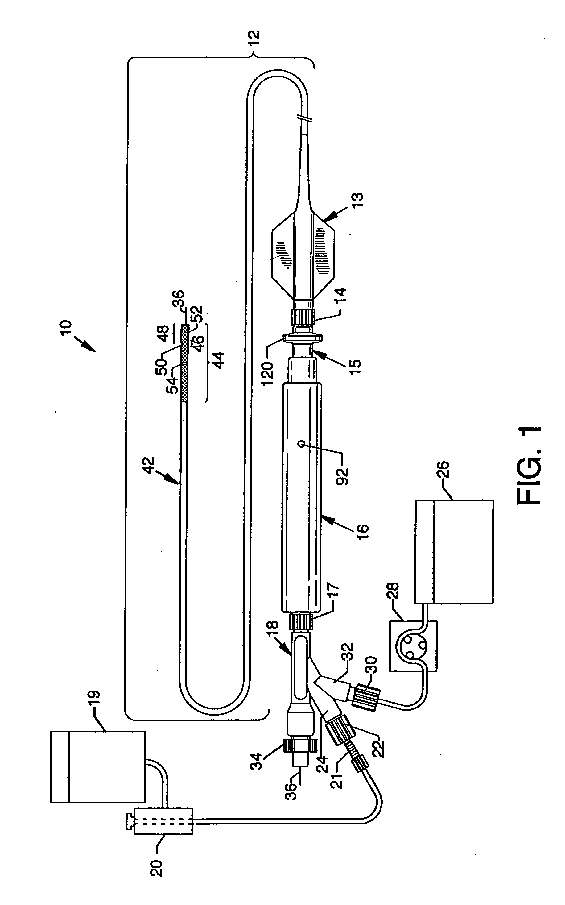
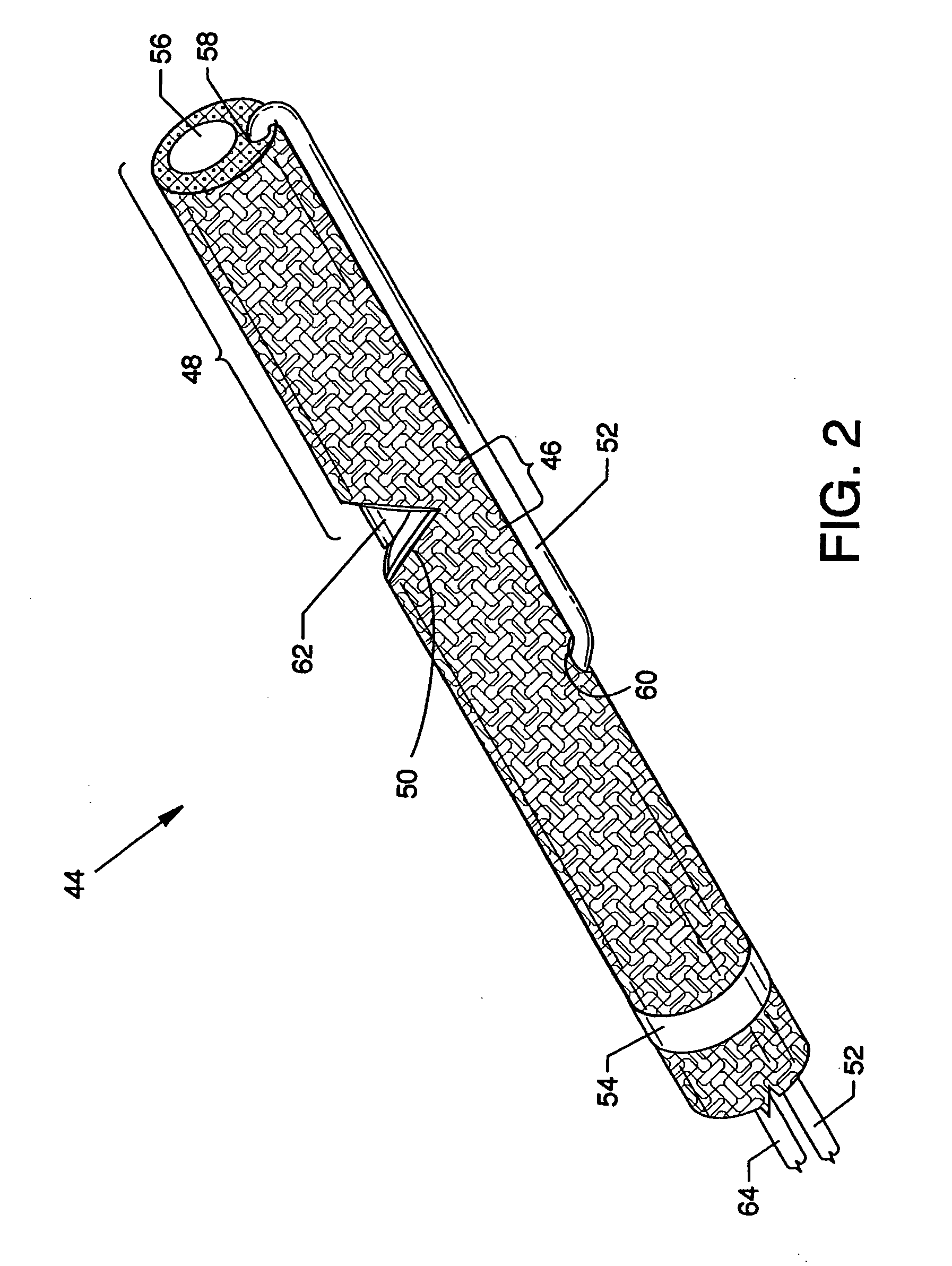
[0062]FIG. 1 is a plan view of an atherectomy system having a variably exposed cutter 10, the present invention. A catheter tube 12 is connected to other aligned and connected components of the system including a hub 13, a connector fitting 14, a slide body 15, a slide tube 16, a connector fitting 17, and a manifold 18. A high pressure fluid source 19 in association with a high pressure fluid pump 20 is suitably connected to a high pressure branch 24 of the manifold 18 by flexible or other tubing and connector fittings 21 and 22. Also suitably connected to the manifold 18 by flexible or other tubing and a connector fitting 30 via an exhaust branch 32 of the manifold 18 is a collection chamber 26 in association with an exhaust regulator 28. A hemostatic nut 34 engages the proximal end of the manifold 18 for suitable sealed interaction with a guidewire 36. The catheter tube 12 has multiple lumens and is formed of a plastic coated nitinol section 42 and a nitinol section 44 without a p...


PUM


Abstract

An atherectomy system having a variably exposed cutter wherein a distally located positionable tip closely associated with the cutter and a high pressure fluid jet emanator can be variably and angularly deployed about a hinge mechanism subsequent to entry into the vasculature. The fixed cutter slices or parts atheromatous material and / or thrombotic material from a blood vessel for interaction with high pressure jets to macerate, break up or otherwise reduce the materials for evacuation from the site.

Description

CROSS REFERENCES TO RELATED APPLICATIONS[0001]This application claims benefit from the earlier filed U.S. Provisional Application No. 60 / 798,961 entitled “Atherectomy System Having a Variably Exposed Cutter”, filed May 9, 2006, and is hereby incorporated into this application by reference as if fully set forth herein.BACKGROUND OF THE INVENTION[0002]1. Field of the Invention[0003]The purpose of the present invention is to provide an improved atherectomy system where treatment of undesirable deposits in the vasculature ranging from soft clots to harder plaque is provided. The major problems faced by current atherectomy devices include vessel safety, embolization, and ease of use. Potentially, all of those issues are addressed by the design of and are incorporated into the operation of the present invention. Coagulated blood, fatty deposits, plaque, grumous or other built-up material generally referred to as thrombus is developed in-vivo in the body. As time goes on, this coagulated b...

Claims


Application Information

Patent Timeline
Patent Type & Authority Applications(United States)
IPC IPC(8): A61B17/22
CPCA61B17/32037A61B17/320708A61B17/32075A61B2017/320791A61B2017/003A61B2017/2927A61B17/320783
Inventor BONNETTE, MICHAEL JOHNTHOR, ERIC JOELWEISEL, STEPHEN EARLMORRIS, DAVID BRIAN
Owner BOSTON SCI LTD
Why Eureka
Try Eureka