

Electrical switching system
a switching system and electrical technology, applied in the field of switching systems, can solve the problems of configuration of insulated switching systems, and achieve the effect of compact construction and low separation distance length
- Summary
- Abstract
- Description
- Claims
- Application Information
AI Technical Summary
Benefits of technology
Problems solved by technology
Method used
Image

Examples
Embodiment Construction
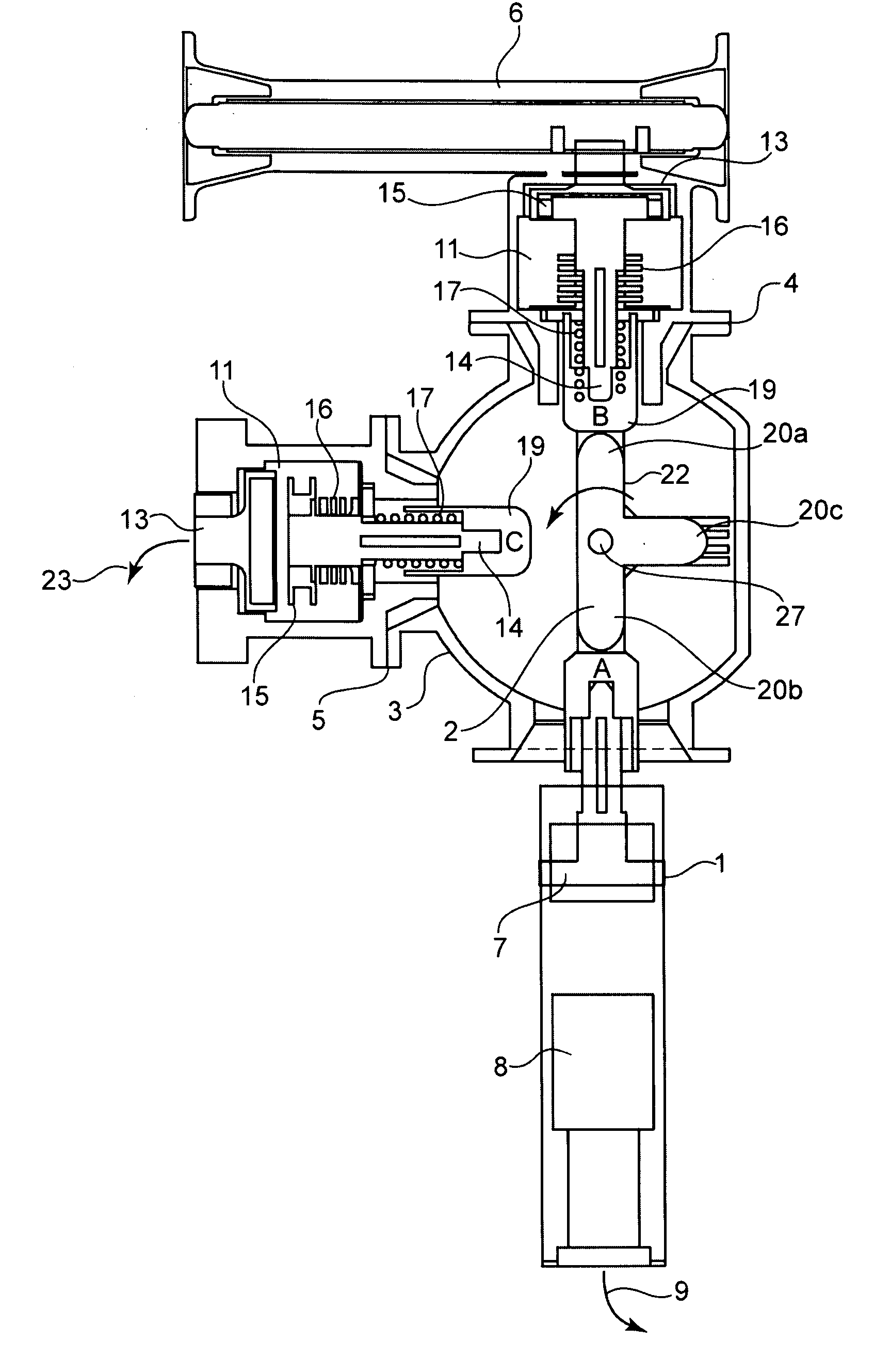
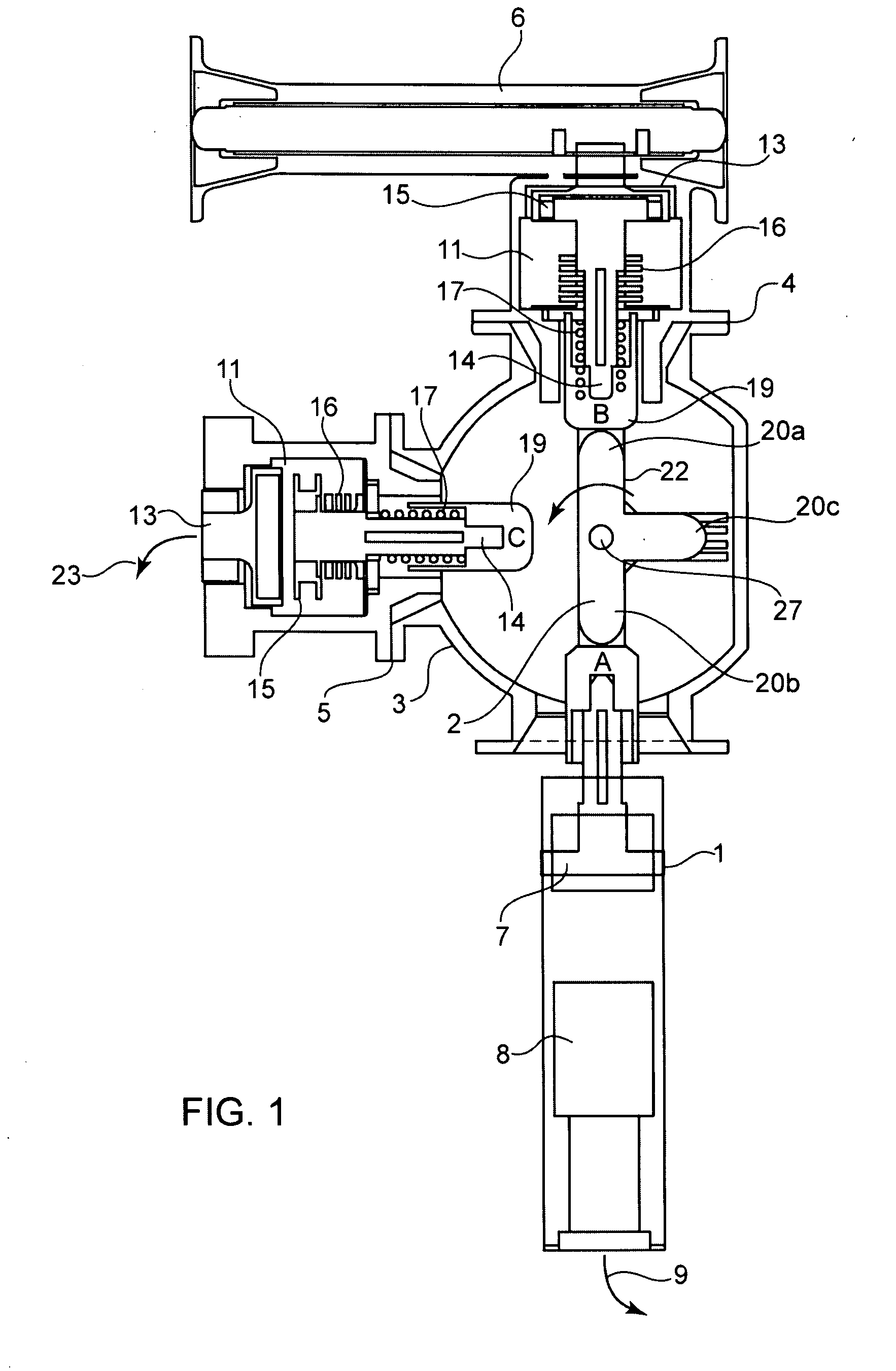
[0031] Referring now in detail to the drawings, FIG. 1 shows a power switch 1, a central switch 2 having a housing 3 that surrounds and encloses this switch, a disconnecting switch 4, a grounding switch 5, and a bus bar 6. All of these elements are components of a switching system, whereby the housing 3 with the central switch 2, the power switch 1, the disconnecting switch 4, and the grounding switch 5 form a switching unit. This switching unit can be disposed in a housing, not shown, which can be filled with an insulating gas that displaces air, N2 or extinguishing gas, particularly SF6 (sulfur hexafluoride). The switching system can therefore be a gas-insulated switching system, particularly for the medium-voltage range, whereby the switching system can furthermore also be an integral part of a switching station or a switching cell. In the present case, however, the switching system is configured as a switching system insulated with solid material, and particularly designed for t...
PUM
 Abstract
Description
Claims
Application Information