
Coaxial RF Device Thermally Conductive Polymer Insulator and Method of Manufacture

a technology of thermal insulation and polymer insulator, which is applied in the direction of insulated conductors, power cables, cables, etc., can solve the problems of increasing the heat generated in such devices, damage or destroy devices, and increasing the amount of heat generated

Active Publication Date: 2007-11-22
COMMSCOPE TECH LLC
View PDF28 Cites 23 Cited by
  • Summary
  • Abstract
  • Description
  • Claims
  • Application Information

AI Technical Summary

Benefits of technology

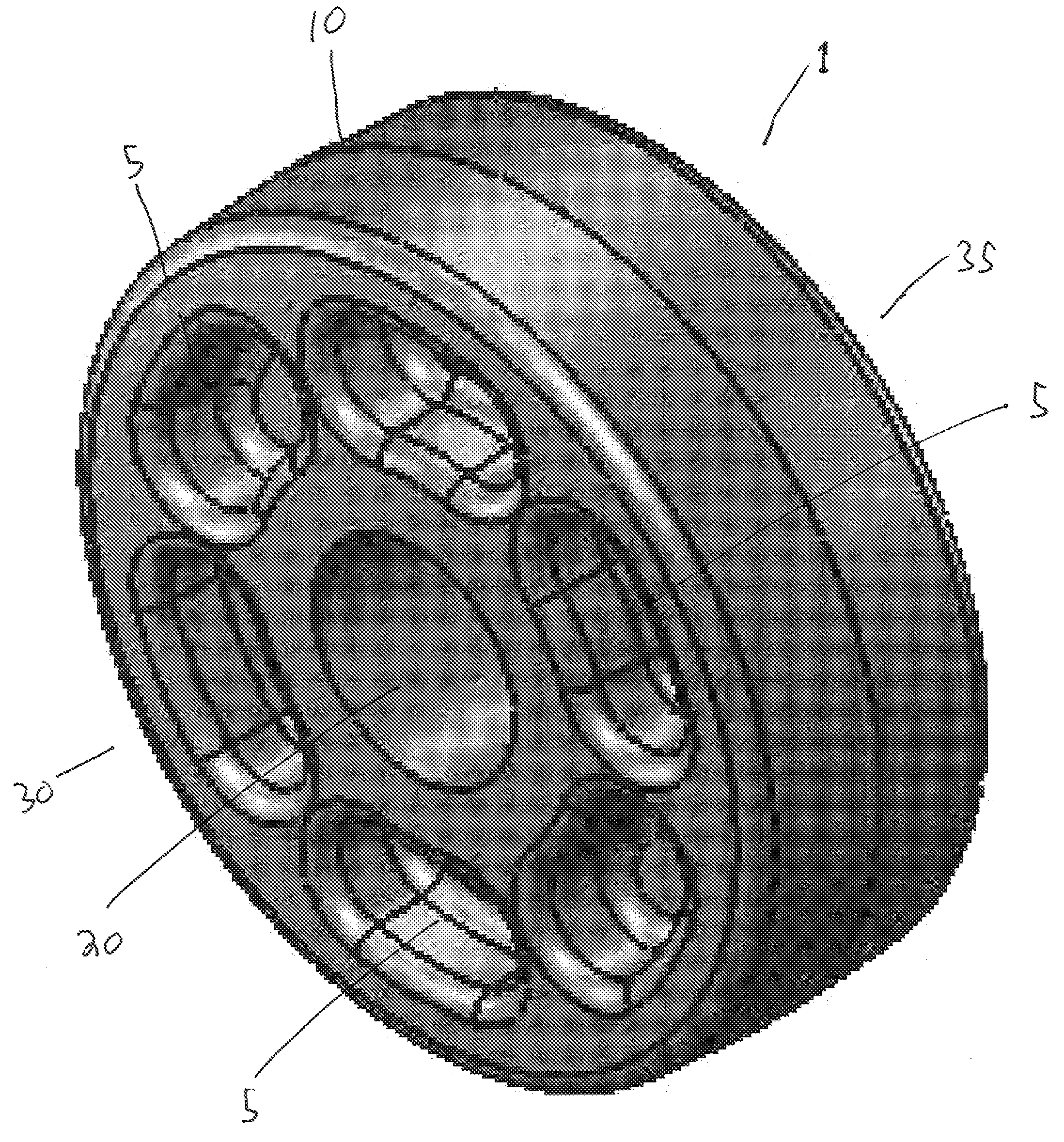
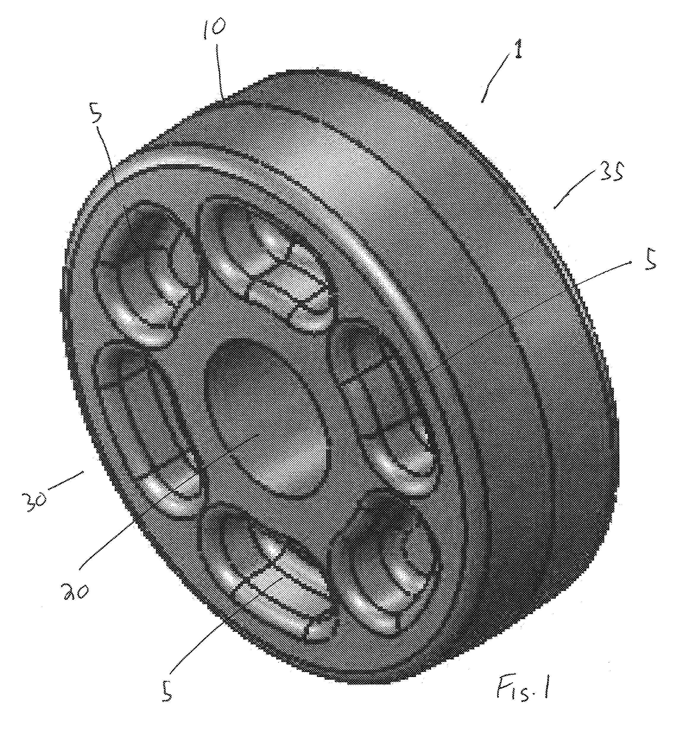
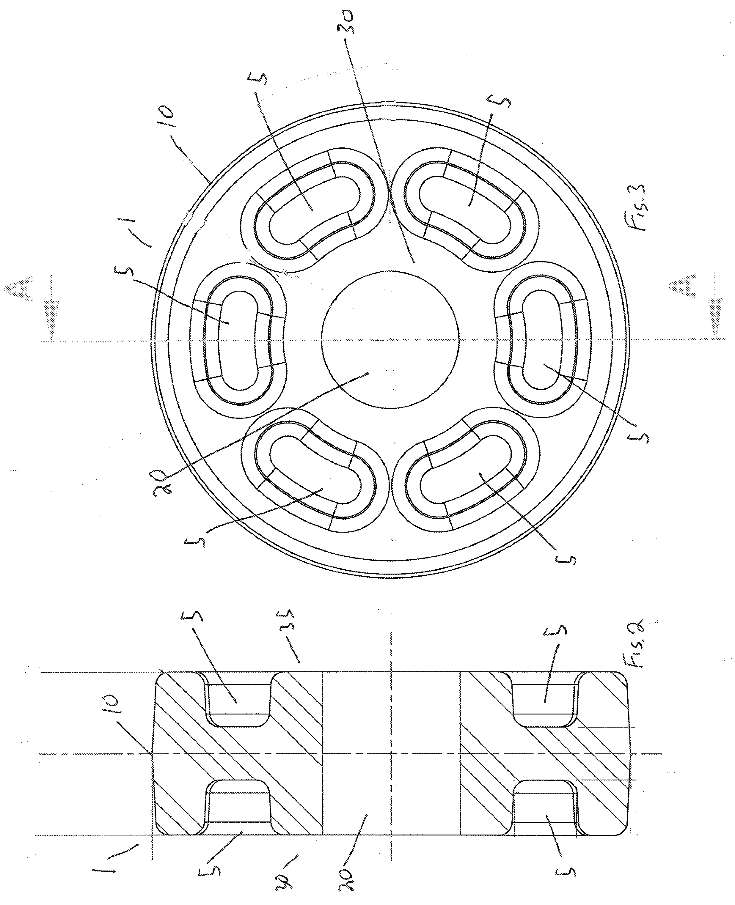
[0019]The inventor has recognized that these insulators and any enclosed air space between the inner conductor and the surrounding outer conductor create an insulated thermal pocket around a section of inner conductor and any devices coupled to the inner conductor there between. In devices according to the invention, the thermal insulating effect of the prior relatively non-thermally conductive insulators may be significantly reduced by application of a thermally conductive polymer composition. The high thermal conductivity capacity of these polymer compositions operates to create a conductive heat transfer path through the insulator to conduct heat away from the inner conductor to the outer conductor that then operates as an effective heat sink to the surrounding ambient atmosphere. By improving heat dissipation of the device, startling power handling capability improvements have been realized.
[0025]One skilled in the art will appreciate that an insulator 10 according to the present invention may be applied to any coaxial RF device 40 where improved heat dissipation, and thereby greater power capacity is desired. For example, the present invention may be applied as the supporting insulator 1 in coaxial portions of antennas and in-line coaxial devices such as surge arrestors, filters, bias-tees, signal taps, DC breaks, connectors or the like. Because heat dissipation and thereby power handling is so dramatically improved, the overall size of the devices may be reduced, further reducing materials costs, overall device weight and installation space requirements.Table of Parts1insulator5cavity10outer periphery15outer conductor20central bore25inner conductor30front end35back end40coaxial RF device45capacitive break50central area

Problems solved by technology

There is an escalation in the amount of power, such as system overlays, that Coaxial RF devices such as RF connectors and surge devices are being required to handle which in turn increases the heat generated in such devices.
In particular, a DC Block or Bias-Tee element applied to the inner conductor of an in-line coaxial device will generate significant heat levels that, if not dissipated, may damage or destroy the device.

Method used


Image

  • Coaxial RF Device Thermally Conductive Polymer Insulator and Method of Manufacture
  • Coaxial RF Device Thermally Conductive Polymer Insulator and Method of Manufacture
  • Coaxial RF Device Thermally Conductive Polymer Insulator and Method of Manufacture

Examples


Embodiment Construction

[0018]In-line coaxial devices utilize insulators to position elements of the inner conductor coaxially within the outer conductor, without electrically coupling the inner and outer conductors. In the prior art, the insulator material was selected primarily based upon the dielectric value, ease of fabrication and cost. Typically, the insulators are polytetrafluoroethylene (PTFE) or polyetherimide (PEI) both of which have advantageous dielectric properties but that are both relatively non-thermally conductive.

[0019]The inventor has recognized that these insulators and any enclosed air space between the inner conductor and the surrounding outer conductor create an insulated thermal pocket around a section of inner conductor and any devices coupled to the inner conductor there between. In devices according to the invention, the thermal insulating effect of the prior relatively non-thermally conductive insulators may be significantly reduced by application of a thermally conductive polym...


PUM


Abstract

An insulator supporting an inner conductor within the outer conductor of a coaxial device formed from a portion of thermally conductive polymer composition with a thermal conductivity of at least 4 W / m-K. The portion is dimensioned with an outer diameter in contact with the outer conductor and a coaxial central bore supporting there through the inner conductor. Cavities may be formed in the portion for dielectric matching and or material conservation purposes. The insulator may be cost effectively fabricated via injection molding.

Description

CROSS REFERENCE TO RELATED APPLICATIONS[0001]This application claims the benefit of U.S. Provisional Patent Application No. 60 / 747,934 filed May 22, 2006 and hereby incorporated by reference in the entirety.BACKGROUND[0002]1. Field of the Invention[0003]The invention generally relates to improvements in the power handling capabilities of inline RF devices for use with coaxial cables. More particularly, the invention relates to methods and apparatus for improving heat dissipation in these devices via thermally conductive insulator(s).[0004]2. Description of Related Art[0005]There is an escalation in the amount of power, such as system overlays, that Coaxial RF devices such as RF connectors and surge devices are being required to handle which in turn increases the heat generated in such devices. In particular, a DC Block or Bias-Tee element applied to the inner conductor of an in-line coaxial device will generate significant heat levels that, if not dissipated, may damage or destroy t...

Claims


Application Information

Patent Timeline
Patent Type & Authority Applications(United States)
IPC IPC(8): H01L29/00H01R24/38
CPCH01P1/30H01P3/06
Inventor VAN SWEARINGEN, KENDRICK
Owner COMMSCOPE TECH LLC
Learn More