Method for enhancing the measuring accuracy when determining the coordinates of structures on a substrate

a technology of coordinates and measuring accuracy, applied in the field of pattern placement metrology, can solve the problems of inability to compensate the interferometer error itself, inability to precisely correct the error, and inability to so as to eliminate the influence of laser interferometer error on the measuring accuracy and increase the measuring accuracy of a measuring system

Active Publication Date: 2007-11-22
VISTEC SEMICON SYST
View PDF7 Cites 13 Cited by
  • Summary
  • Abstract
  • Description
  • Claims
  • Application Information

AI Technical Summary

Benefits of technology

[0017]An object of the present invention is to increase the measuring accuracy of a measuring system for the determination of positions of structures on a substrate and, at the same time, to eliminate the influence of the laser interferometer error on the measuring accuracy.

Problems solved by technology

There are strong indications that a significant error component of the LMS IPRO, manufactured by Vistec Semiconductor System GmbH of Wetzlar, Germany, is caused by the interferometer error.
This error is caused by the Agilent interferometer system.
Since the reflection angle can vary slightly due to the mirrors on the stage body and the moveability of the stage body itself, and therefore the places of incidence of the laser beams in the interferometer as well as the superposition of measuring and reference beam are changed, so the amplitude and phase of the interferometer error also changes.
While the change in the refractive index measured by the etalon correctly takes the associated position change into account, also over longer distances, it cannot compensate the interferometer error itself.
The correction of this error is therefore not precisely possible since it changes not only as a function of the measuring place on the mask but also over time.

Method used


Image

  • Method for enhancing the measuring accuracy when determining the coordinates of structures on a substrate
  • Method for enhancing the measuring accuracy when determining the coordinates of structures on a substrate
  • Method for enhancing the measuring accuracy when determining the coordinates of structures on a substrate

Examples


Embodiment Construction

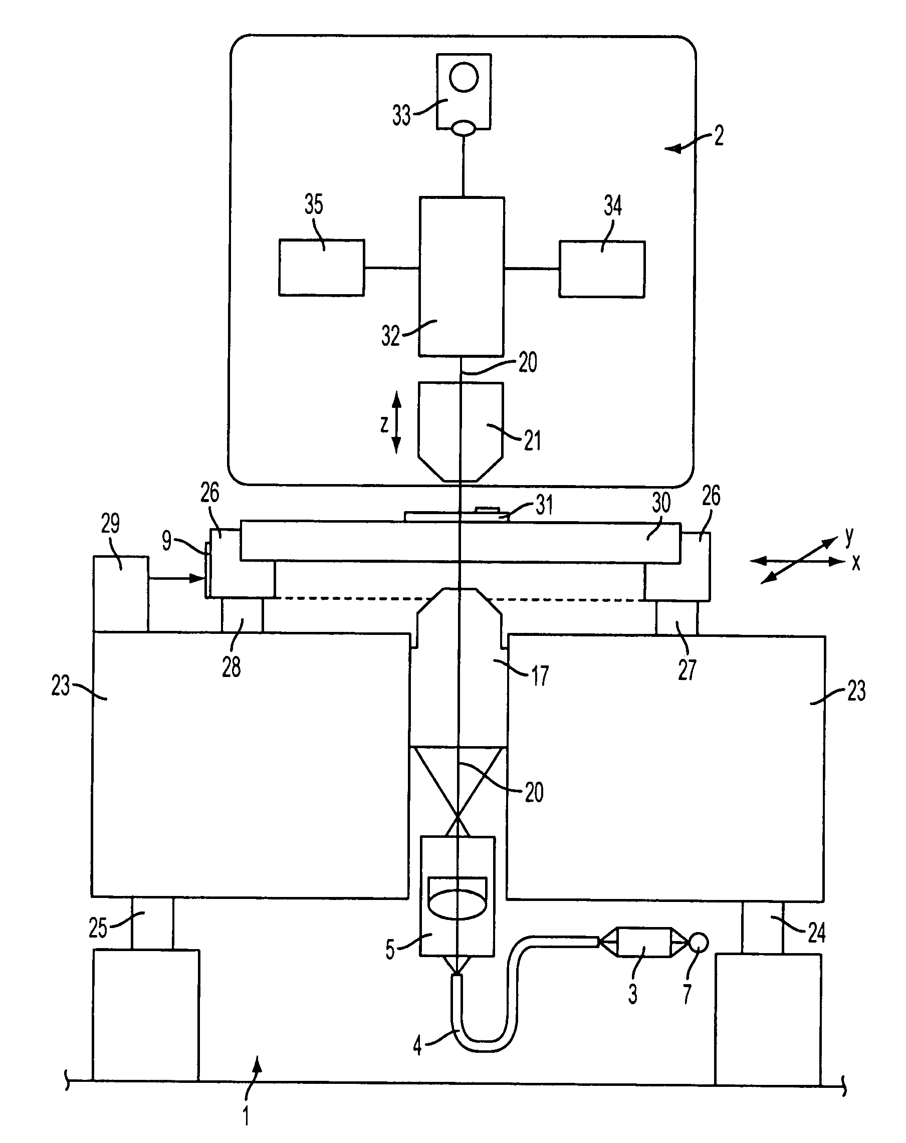
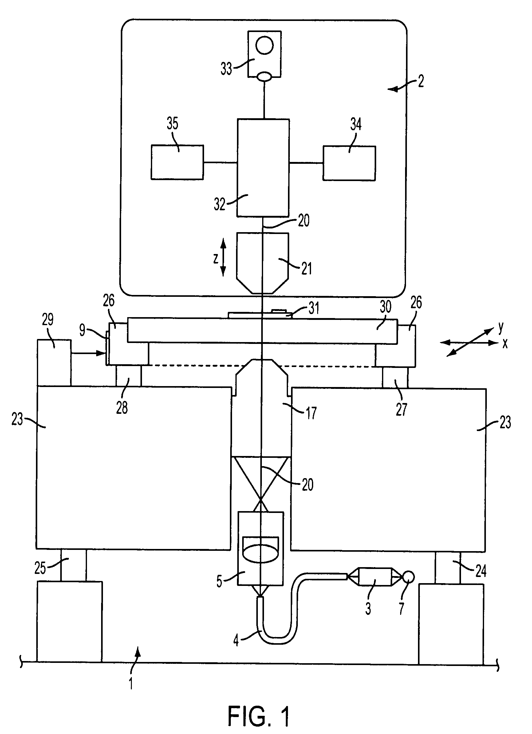
[0051]A coordinate measuring device of the type shown in FIG. 1 has already been explained in detail in the introductory portion of the description.

[0052]The repeatability or reproducibility of such a coordinate measuring device is usually determined in the factory by measuring a measurement grid of 15 by 15 points (measuring area 6 inches, 152×152 mm). The value of the threefold standard deviation (3σ) is typically determined after 20 measurements for the coordinates obtained in the X and Y coordinate directions. The maximum value of this threefold standard deviation represents the repeatability and therefore the machine performance.

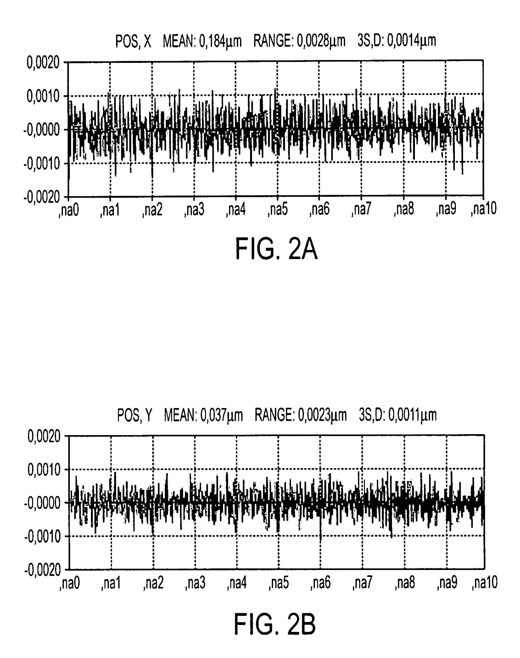
[0053]If the measurements are made locally on a defined mask position, i.e. in this case the X / Y measuring stage is not traversed, this is an indication for short-term reproducibility (here 20*100 measurements*4 sec=2.2 hours). This measurement gives an indication on the repeatability within a short period of time (so-called needle test).

[0054]The resul...


PUM


Abstract

A method for the high-precision measurement of coordinates of at least one structure on a substrate. A stage traversable in X / Y coordinate directions is provided, which is placed in an interferometric-optical measuring system. The structure on the substrate is imaged on at least one detector (34) via a measuring objective (21) having its optical axis (20) aligned in the Z coordinate direction. The structure is imaged with the so-called Dual Scan. Systematic errors can thereby be eliminated.

Description

[0001]This claims the benefit of German patent application DE 10 2006 023 151.1, filed May 16, 2006 and of German patent application DE 10 2007 017 630.0, filed Apr. 12, 2007, and hereby incorporated by reference herein.[0002]The present invention relates to a method for the high-precision measurement of coordinates of at least one structure on a substrate placed on a stage moveable in X / Y coordinate directions in an interferometric-optical measuring system. The structure on the substrate is imaged onto a detector via a measurement objective having its optical axis aligned in the Z coordinate direction.BACKGROUND[0003]A measuring device as used for measuring structures on substrates (wafers or masks) has been described in detail in the paper entitled “Pattern Placement Metrology for Mask Making” held by Dr. Carola Blasing at the Semicon Education Program Convention in Geneva on Mar. 31, 1998. The description given there is the basis of a coordinate measuring device. Since the presen...

Claims


Application Information

Patent Timeline
Patent Type & Authority Applications(United States)
IPC IPC(8): G01B11/02G01B11/00
CPCG03F7/70775G01B9/02007G01B2290/60G01B9/02084G01B2290/25G01B2290/70
Inventor BOESSER, ARTURSCHAAF, ANDREAS
Owner VISTEC SEMICON SYST
Why Eureka
Try Eureka