Ald Apparatus and Method

a technology of al applied in the direction of vacuum evaporation coating, chemically reactive gas, crystal growth process, etc., can solve the problems of short equipment uptime, deterioration of performance of existing ald apparatus, and inability to cost-effectively implement ald systems and methods for manufacturing semiconductor devices and other devices, etc., to enhance the advantages of smfd-ald apparatus and method, improve film quality, and enhance material utilization efficiency

Inactive Publication Date: 2007-11-22
SUNDEW TECH
View PDF47 Cites 374 Cited by
  • Summary
  • Abstract
  • Description
  • Claims
  • Application Information

AI Technical Summary

Benefits of technology

[0019] Embodiments in accordance with the invention provide improved apparatus and method to further enhance the advantages of SMFD-ALD apparatus and method. In one embodiment, the invention provides a method of conducting atomic layer deposition with enhanced material utilization efficiency. In that method, chemical dosage is conducted in a dose and hold mode. During the hold mode, the flow of chemical into the process chamber is terminated while the flux is effectively maintained. This mode is beneficial for the final stages of chemical dose where chemical depletion is minimal, while maintaining chemical flux can further promote the reaction far into saturation to much improve film quality.

Problems solved by technology

Multiple technical challenges have so far prevented cost-effective implementation of ALD systems and methods for manufacturing of semiconductor devices and other devices.
Existing ALD apparatuses have also struggled with performance deterioration caused by extensive growth of inferior films on the walls of the ALD chambers.
This performance deterioration facilitated short equipment uptime and high cost of maintenance.
Existing ALD apparatuses have struggled with performance deterioration related to slit-valve induced asymmetry with its unavoidable dead-leg cavity.
Both of these prior art solutions and other prior art solutions are not ideally suited to resolve the slot valve cavity problem in ALD systems.
However, the ring slit-valve described in U.S. Pat. No. 6,347,919 presents significant performance deterioration that is associated with the presence of unprotected elastomeric seals and the respective crevices between the slide of the ring slit-valve and the chamber wall that is notorious for entrapment of chemicals and the growth of deposits and particulates on the seal and within the crevices.
While deterioration of chamber performance related to growth of deposits on slit-valve seals is a universal problem with all existing designs of slit valves, ring-shaped slit-valves as taught in U.S. Pat. No. 6,347,919 substantially aggravate that problem due to substantially longer seals and crevices.
Unfortunately, this performance limitation makes the ring-shaped slit-valve that was taught in U.S. Pat. No. 6,347,919 practically unusable for ALD applications.
Chemical delivery into ALD chambers has been generally been limited to chemicals with substantial vapor pressure.
Accordingly existing ALD systems have struggled with the challenge of consistent chemical delivery of low-volatility molecular precursors as abruptly shaped doses for promoting high productivity ALD processes.

Method used


Image

  • Ald Apparatus and Method
  • Ald Apparatus and Method
  • Ald Apparatus and Method

Examples


Embodiment Construction

[0063] The invention is described herein with reference to FIGS. 1-22. For the sake of clarity, the same reference numerals are used in several figures to refer to similar or identical components. It should be understood that the structures and systems depicted in schematic form in FIGS. 1-22 serve explanatory purposes and are not precise depictions of actual structures and systems in accordance with the invention. Furthermore, the embodiments described herein are exemplary and are not intended to limit the scope of the invention, which is defined in the invention summary and in the claims below.

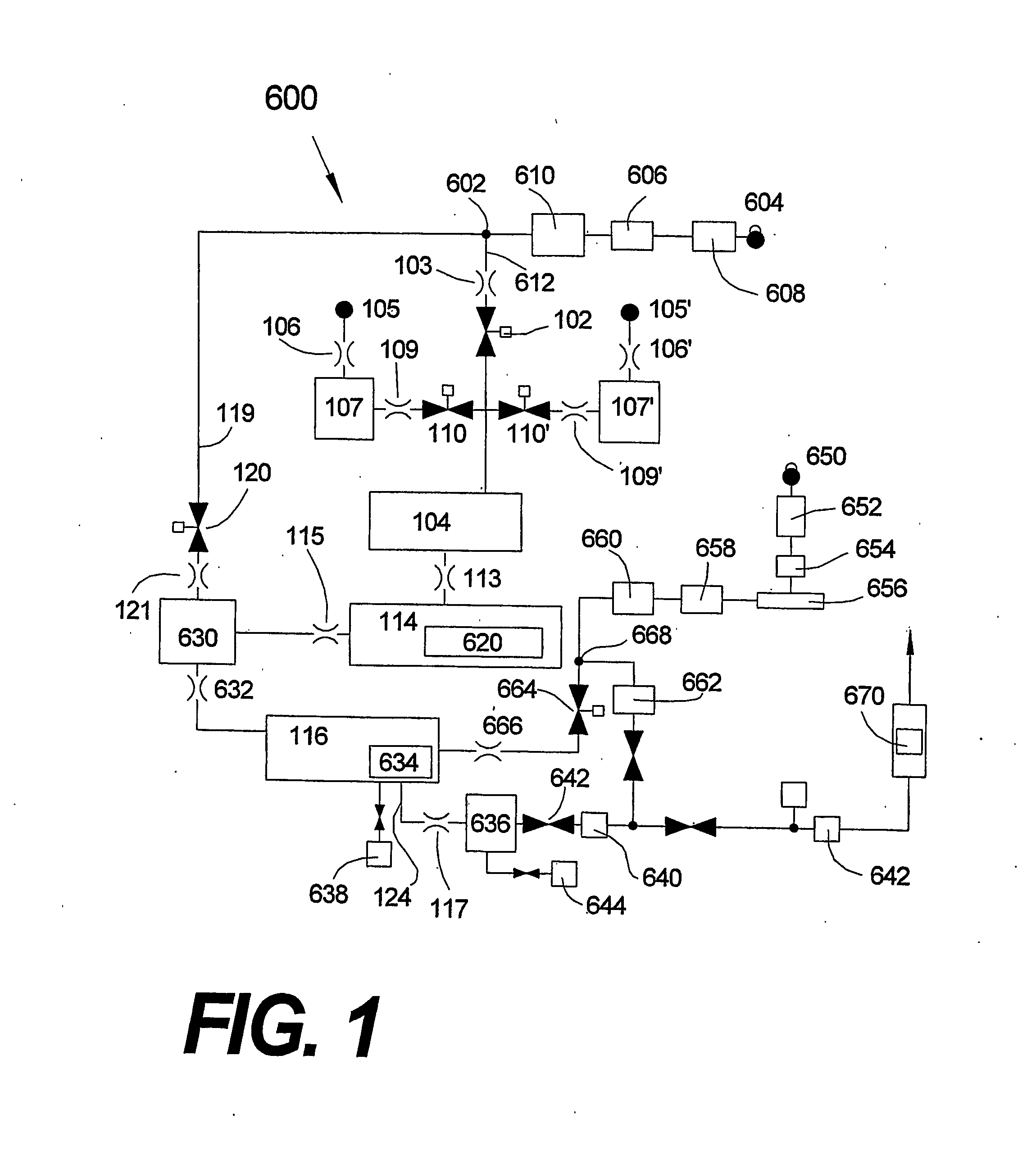
[0064]FIG. 1 depicts a flow diagram of a basic embodiment of a synchronously modulated flow-draw (“SMFD”) ALD system 600 in accordance with the invention described in U.S. patent application Ser. No. 10 / 347575, PCT Application No. US03 / 01548, and the improvements that are disclosed in this application.

[0065] System 600 comprises a pressure-stabilized inert, purge-gas source 602 of a purge ...


PUM

PropertyMeasurementUnit
thicknessaaaaaaaaaa
response timeaaaaaaaaaa
temperaturesaaaaaaaaaa

Abstract

Improved apparatus and method for SMFD ALD include a method designed to enhance chemical utilization as well as an apparatus that implements lower conductance out of SMFD-ALD process chamber while maintaining full compatibility with standard wafer transport. Improved SMFD source apparatuses (700, 700′, 700″) and methods from volatile and non-volatile liquid and solid precursors are disclosed, e.g., a method for substantially controlling the vapor pressure of a chemical source (722) within a source space comprising: sensing the accumulation of the chemical on a sensing surface (711); and controlling the temperature of the chemical source depending on said sensed accumulation.

Description

BACKGROUND OF THE INVENTION [0001] 1. Field of the Invention [0002] This invention relates to the field of atomic layer deposition (“ALD”), and more particularly to apparatus and methods for performing ALD with high throughput and low cost. [0003] 2. Description of Prior Art [0004] Thin film deposition is commonly practiced in the fabrication of semiconductor devices and many other useful devices. An emerging deposition technique, atomic layer deposition (ALD), offers superior thickness control and conformality for advanced thin film deposition. ALD is practiced by dividing conventional thin-film deposition processes into single atomic-layer deposition steps, named cycles, that are self-terminating and deposit precisely one atomic layer when conducted up to or beyond self-termination exposure times. The deposition per cycle during an ALD process, the atomic layer, typically equals about 0.1 molecular monolayer to 0.5 molecular monolayer. The deposition of atomic layer is the outcome...

Claims


Application Information

Patent Timeline
Patent Type & Authority Applications(United States)
IPC IPC(8): B05C11/00H01L21/302C23C16/00C23C16/44C23C16/448C23C16/455C30B25/14
CPCC23C16/4409C23C16/4488Y10T117/1004C23C16/45557C30B25/14C23C16/45544
Inventor SNEH, OFER
Owner SUNDEW TECH
Why Eureka
Try Eureka