Integrated power window and skylight operating systems

a technology of operating system and power window, which is applied in the direction of wing operation mechanism, door/window fitting, etc., can solve the problems of difficulty in installation, damage to the operator, hardware or unit, and the operator system may not be easily usable with windows or skylights, so as to prevent damage to the system, hardware, window or skylight, and facilitate installation. , the effect of saving energy

Inactive Publication Date: 2007-11-29
TRUTH HARDWARE
View PDF30 Cites 39 Cited by
  • Summary
  • Abstract
  • Description
  • Claims
  • Application Information

AI Technical Summary

Benefits of technology

[0009] The present invention addresses the need of the industry for an easily installable power operator system for windows and skylights. The present invention also assists in energy savings by permitting a home owner or building operator to take advantage of passive cooling controlled by automation. In addition, the present invention senses the temperature at the location of a remote control that can follow the occupants of the structure wherever they might be so that a desired temperature can be achieved where the people actually are located.
[0010] In a preferred embodiment of the invention, a power operator and control system includes means for automatically determining the physical travel limits of a particular window or skylight on which the system is installed and automatically varying the motor torque to prevent damage to the system, hardware, window, or skylight.
[0011] In further preferred embodiments of the invention, the operator and control system includes a DC regulated power supply along with means enabling direct application of AC power at any common voltage or frequency. It is thereby unnecessary to ensure that AC power of any specific voltage or frequency is available at the site where the operator system is to be installed, greatly enhancing ease of installation.
[0012] Also, other preferre...

Problems solved by technology

A problem with prior motorized operator systems, however, is that they have typically been difficult to install.
If these limits are not properly determined and set, the operator may continue to run and apply force to the skylight or window after it has reached the full physical limit of its travel, thereby causing damage to the operator, hardware, or unit.
Another installation problem a...

Method used


Image

  • Integrated power window and skylight operating systems
  • Integrated power window and skylight operating systems
  • Integrated power window and skylight operating systems

Examples


Embodiment Construction

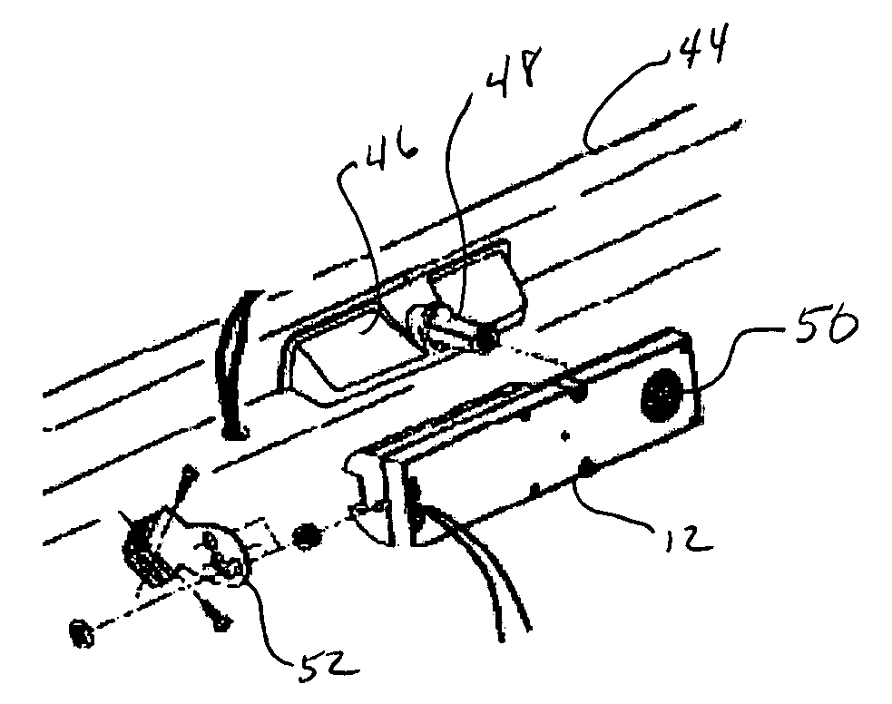
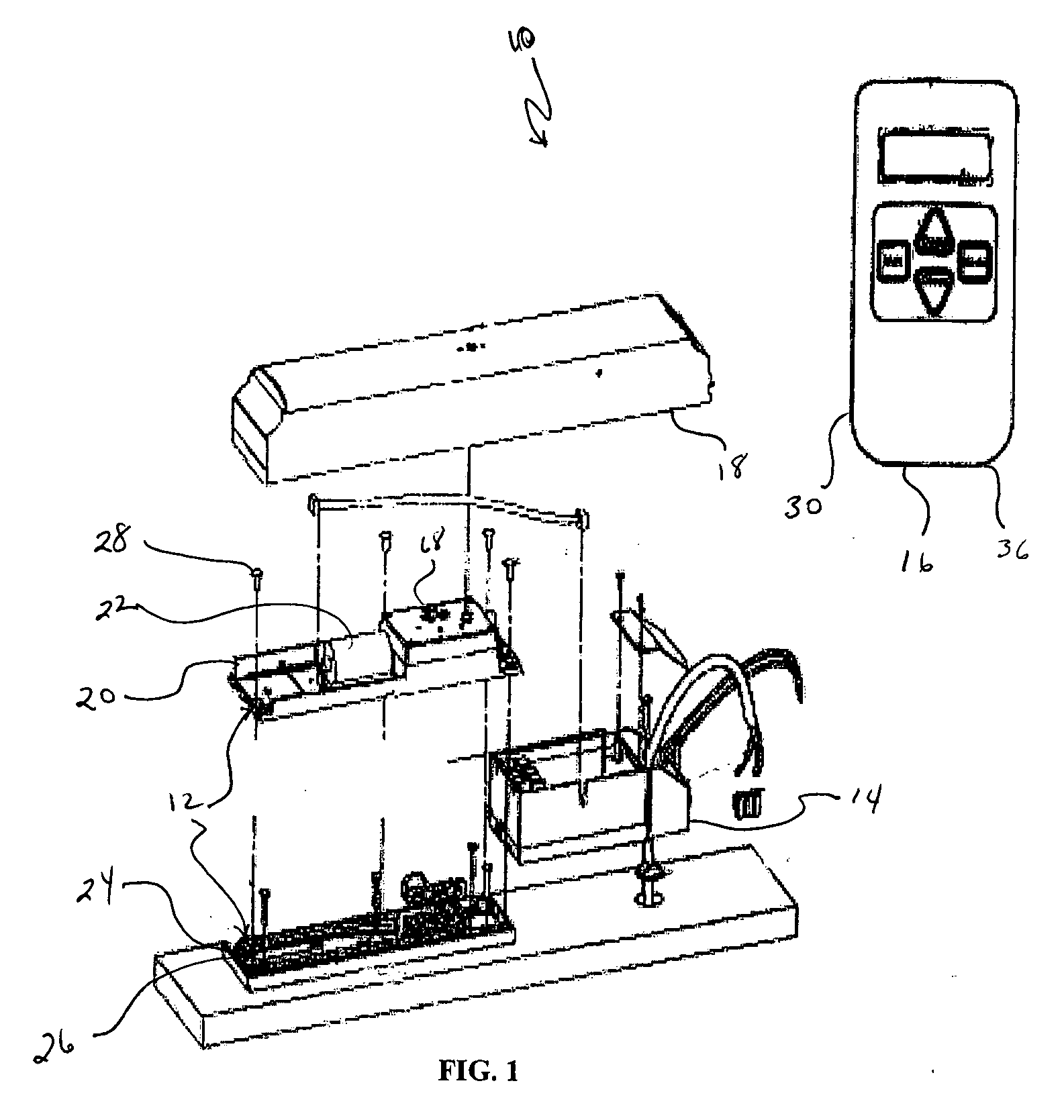
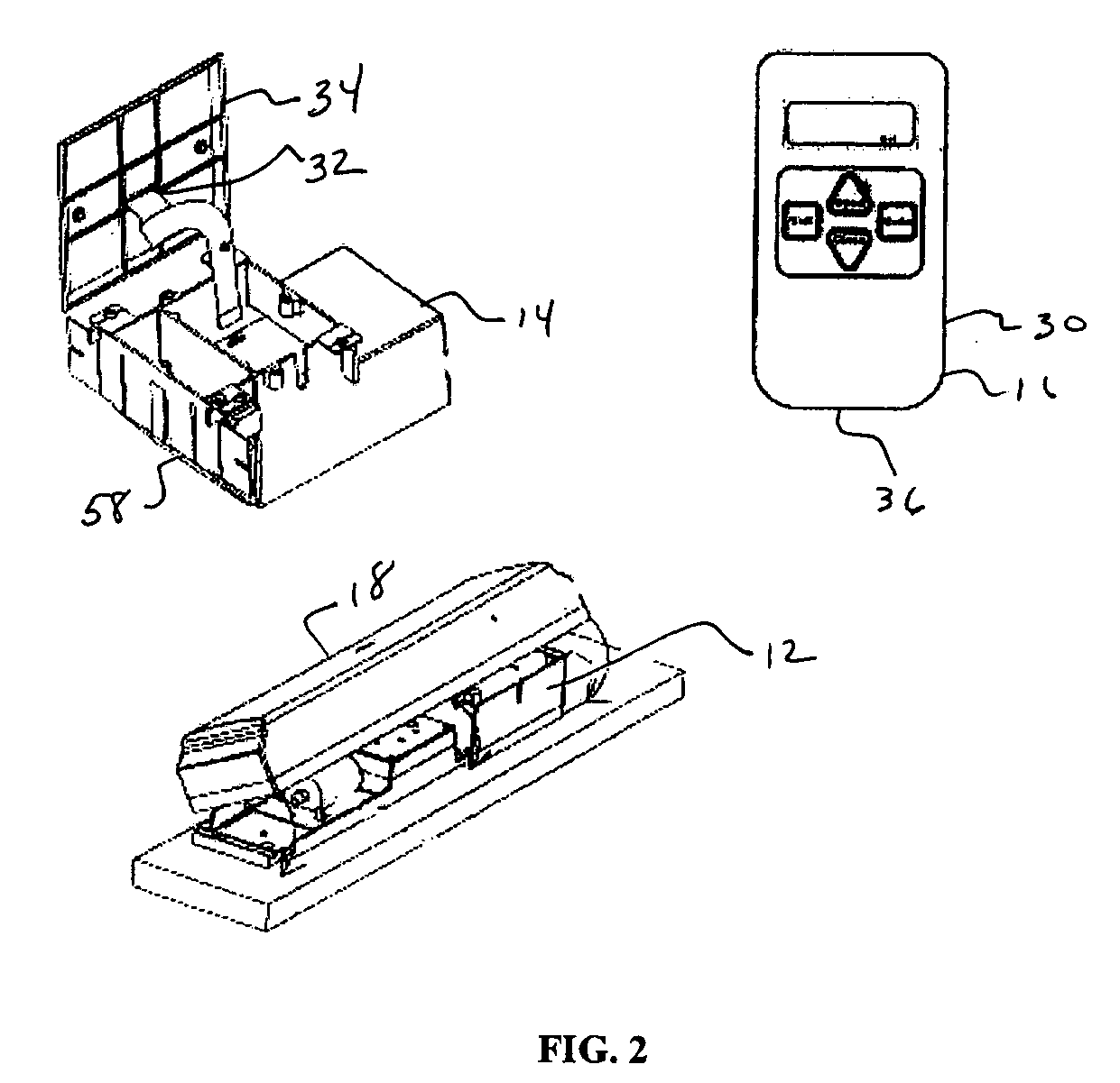
[0023]FIGS. 1 and 8 depict a motorized window and skylight operator system 10 according to the present invention. The motorized window and skylight operator system 10 generally includes a motorized operator 12 and an operator control unit 14. Optionally, the system 10 may include a remote control unit 16 for wirelessly controlling the system from a remote location. In the depicted embodiment, the motorized operator 12 generally includes an operator cover 18, an upper portion 20 having a motor 22, and a lower portion 24 having a chain drive 26. Other drives may also be used as will be recognized by those skilled on the art. The upper portion 20 may be coupled with the lower portion 24 by fasteners 28 such as screws. The operation and further details of the motorized operator 12 are disclosed in U.S. Pat. Nos. 4,521,993 and 4,945,678, both previously incorporated herein by reference.

[0024] In the context of this application the term fenestration is to be construed to include but not ...


PUM


Abstract

An operable fenestration operating system for a structure including a window or skylight having a frame, an operable sash and presenting a resistance force opposing opening and closing of the sash. A motorized operator is coupled with the frame and the sash to selectively open and close the sash. The invention includes an operator control unit communicatively connected to the motorized operator. The operator control unit includes a processor, a sensor for sensing the magnitude of the resistance force, a pulse width modulation circuit for supplying electrical power to the motorized operator. The processor varies the torque output of the motorized operator using the pulse width modulation circuit in response to the sensed parameter.

Description

CLAIM TO PRIORITY [0001] This application claims priority to U.S. Provisional Application Ser. No. 60 / 552,777 entitled “Improved Integrated Power Window And Skylight Operating Systems” filed Mar. 12, 2004. That Provisional Application is incorporated herein in its entirety by reference.FIELD OF THE INVENTION [0002] This invention relates to power window and skylight operating systems. BACKGROUND OF THE INVENTION [0003] Motorized window and skylight operator systems have existed in the market for a number of years. In general, these motorized window and skylight operator systems include a motorized operator and an operator control unit. Optionally, these systems may have at least a system control unit. Examples of such operator systems are shown, for example, in U.S. Pat. Nos. 4,136,578; 4,241,541; 4,253,276; 4,266,371; 4,305,228; 4,346,372; 4,497,135; 4,521,993; 4,617,758; 4,823,508; 4,840,075; 4,843,703; 4,845,830; 4,894,902; 4,937,976; 4,938,086; 4,945,678; 5,054,239; 5,152,103; 5...

Claims


Application Information

Patent Timeline
IPC IPC(8): E05F15/20
CPCE05F15/70E05Y2900/154
Inventor WOLF, GLENDALLMANN, BRIANBRAUN, PETERSOUKUP, THOMAS
Owner TRUTH HARDWARE
Why Eureka
Try Eureka