Engine exhaust emission control system providing on-board ammonia generation

an exhaust system and ammonia generation technology, applied in the direction of machines/engines, mechanical equipment, chemistry apparatus and processes, etc., can solve the problems of high engine-out emissions of nox and pm, limited acceptance of compression-ignition engines and direct-injection spark-ignition engines, and low engine-out emissions of co and h

Inactive Publication Date: 2007-11-29
DELPHI TECH INC
View PDF10 Cites 102 Cited by
  • Summary
  • Abstract
  • Description
  • Claims
  • Application Information

AI Technical Summary

Benefits of technology

[0014] The present invention is directed to an exhaust emission control system that provides on-board ammonia generation and comprises: a NOx sensor for detecting NOx in exhaust gas from an engine; a lean NOx trap (LNT) for removing and retaining NOx from engine exhaust gas; an on-board reformer for providing reformate fuel to the system; a first conduit for conveying reformate fuel from the on-board reformer to the LNT, where the reformate fuel reacts with NOx retained in the LNT, reducing the NOx and thereby forming NH3; a selective catalytic reduction (SCR) catalyst disposed downstream of the LNT for catalytically reducing NOx; a second conduit by-passing said LNT that conveys said engine exhaust gas to said

Problems solved by technology

Acceptance of compression-ignition engines and direct-injection spark-ignition engines has been limited due to the inability to comply with increasingly strict emissions regulations.
When compression-ignition engines and direct-injection spark ignition engines operate with a fuel charge that is at an air/fuel ratio that is lean of stoichiometry, the result is low engine-out emissions of CO and HC.
However, lean operation also typically results in higher levels of engine-out emissions of NOx and PM.
If this does not occur, the catalyst eventually becomes saturated, leading to breakthrough of NOx emissions.
Currently available NOx adsorber catalysts perform optimally when the

Method used


Image

  • Engine exhaust emission control system providing on-board ammonia generation
  • Engine exhaust emission control system providing on-board ammonia generation

Examples


Embodiment Construction

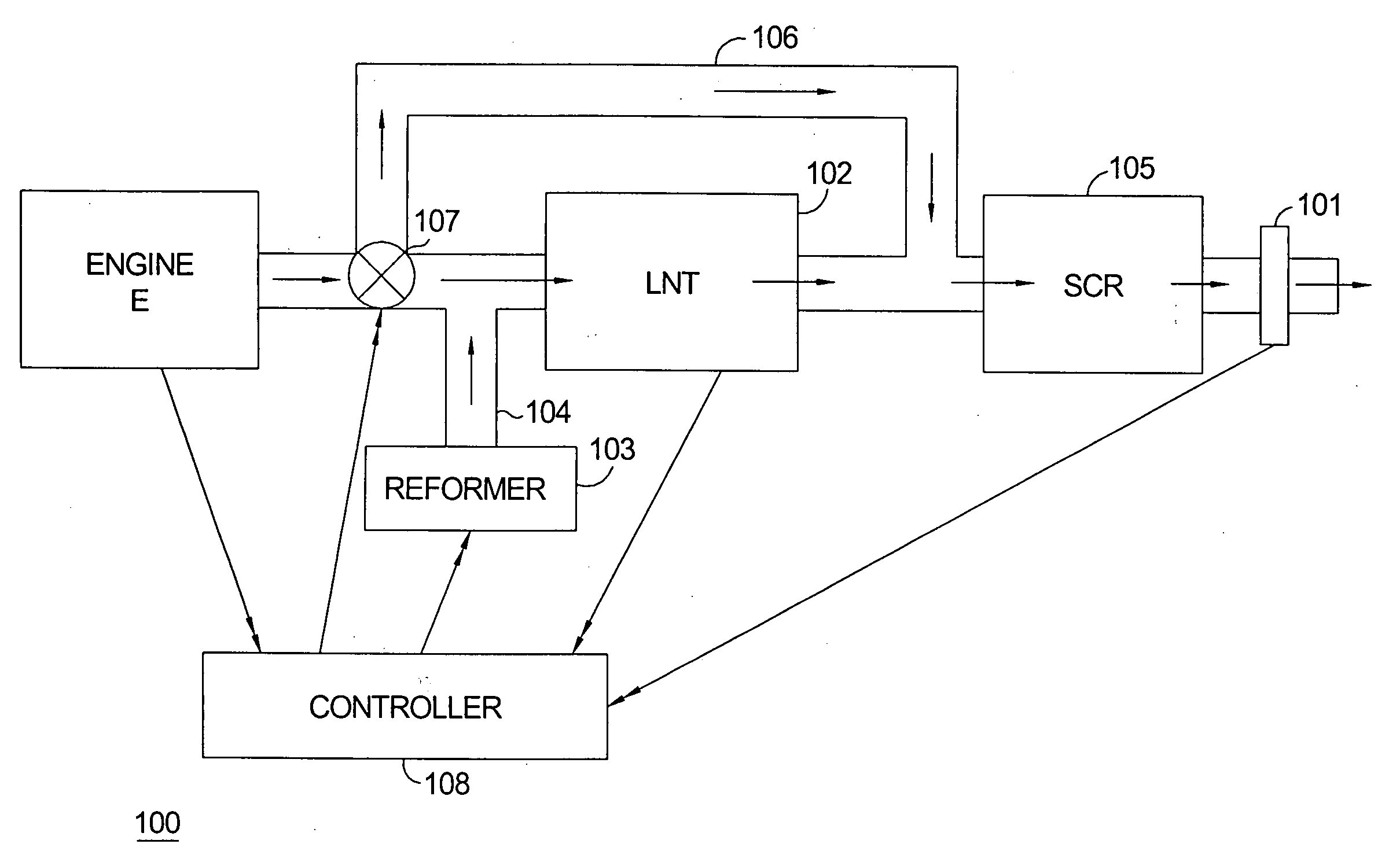
[0019] The exhaust emission control system of the present invention provides on-board ammonia generation and includes an upstream 3-way bypass valve, a lean NOx trap (LNT), and a selective catalytic reduction (SCR) catalyst. Reformate from an on-board reformer is injected into the LNT to react with NOx accumulated thereon, converting it to ammonia and thereby regenerating the LNT. During this process of LNT regeneration and accompanying ammonia production, the exhaust flow is directed by the upstream valve around the LNT and into the downstream SCR catalyst. When the valve is repositioned to allow the exhaust to again pass through the LNT, the ammonia generated in the LNT is directed to the SCR catalyst to promote NOx reduction there.

[0020] The following chemical reactions occur in the various components of the exhaust emission control system of the present invention:

Reformer: diesel fuel+air→H2+CO

LNT: 2NO+5H2→2NH3+2H2O

SCR catalyst: 6NO+4NH3→5N2+6H2O

[0021] Referring to FIG. 1, ...


PUM


Abstract

An exhaust emission control system that provides on-board ammonia generation includes a valve disposed upstream of the LNT and SCR catalyst that operates to selectively control the flow of engine exhaust gas to an LNT and/or an SCR catalyst; while reformate fuel is being conveyed from a reformer to the LNT, the valve operates to cause the exhaust gas to bypass the LNT and flow directly to the SCR catalyst. The exhaust emission control system further includes a controller provided with an algorithm that monitors engine operating conditions and exhaust gas conditions, estimates the cumulative amount of exhaust gas created by the engine and the amount of NOx stored in the LNT, and calculates the amount of NOx required to be converted to NH3.

Description

TECHNICAL FIELD [0001] This invention relates generally to engine exhaust systems and more particularly to an exhaust system that provides on-board ammonia generation. BACKGROUND OF THE INVENTION [0002] Internal combustion engines, including compression ignition engines and spark ignition engines regularly undergo redesign efforts to improve efficiency and enhance fuel economy. Compression-ignition engines and direct-injection spark-ignition engines are gaining in popularity due in part to improved fuel economy, which may exceed 20% improvement compared to a similarly-sized, conventional spark-ignition engine. Compression-ignition engines and direct-injection spark-ignition engines operate with excess air in the combustion process, which is also referred to as operating lean of stoichiometry. An engine that operates lean of stoichiometry can do so without a throttle valve in the air intake manifold. Stoichiometry is an air / fuel ratio at which there is a sufficient amount of oxygen f...

Claims


Application Information

Patent Timeline
IPC IPC(8): F01N3/00F01N3/10
CPCF01N3/0814F01N3/0842F01N3/0878F01N3/2073F01N11/00F01N13/009F01N2410/00F01N2560/026F01N2610/03Y02T10/47Y02T10/24F01N2240/30Y02T10/12Y02T10/40
Inventor HEMINGWAY, MARK D.CHRISTOPHER, BRIAN J.THORNTON, MICHAEL P.
Owner DELPHI TECH INC
Why Eureka
Try Eureka