Combustion Apparatus and Combustion Method

a combustion apparatus and combustion method technology, applied in the direction of combustion types, lighting and heating apparatus, machines/engines, etc., can solve the problems of inability to premix liquid fuel, the most difficult to reduce thermal nox, and the most likely to occur backfire or blow-off, etc., to maximize the effect of burnt gas recirculation, suppress thermal nox generation, and enhance stability

Inactive Publication Date: 2007-11-29
EBARA CORP
View PDF3 Cites 100 Cited by
  • Summary
  • Abstract
  • Description
  • Claims
  • Application Information

AI Technical Summary

Benefits of technology

[0060] Further, in the gas turbine combustion apparatus to which the combustion apparatus of the present invention is applied, it is possible to enhance the stability and maximize effects of burnt gas recirculation. Accordingly, it is possible to suppress generation of thermal NOx in a case of liquid fuel, in which it has been difficult to reduce NOx with the conventional technology.
[0061] As described above, in the combustion apparatus of the present invention, since an inner wall of the combustion apparatus is suitably cooled by an air flow having a low temperature, it is possible to provide a gas turbine combustion apparatus having a high durability.
[0062] Further, in the combustion apparatus of the present invention, because of a simple structure, it is possible to provide a gas turbine combustion apparatus which can readily use a heat resistant material such as ceramics,

Problems solved by technology

As compared to the aforementioned reduction of fuel NOx and prompt NOx, reduction of thermal NOx is most difficult and is becoming a key of NOx reduction technology in recent years.
However, premixed combustion has problems that a stable combustion range is so narrow that backfire or blow-off is likely to occur.
Further, there is a defect that liquid fuel cannot be premixed unless the fuel has previously been evaporated (pre-evaporated).
Thus, there is a limit to reduction of thermal NOx.
However, the size of the combustion apparatus problematically becomes large by the pre-evaporation portion.
However, such technology has been employed in many large-sized combustion furnaces but cannot be applied to small-sized combustion apparatuses because a supply system of fuel or air becomes complicated.
Further, it is difficult to find optimal supply locations of fuel or air and optimal division ratios, or to control these locations and division ratios according to loads.
However, a burnt gas recirculation flow centrally downstream of the flame holding plate does not reach a portion in which fuel is mixed with air before ignition.
Accordingly, this technology is not suited for purposes of a combustion apparatus of a gas turbine or the like where the size of a combustion chamber should be made as small as possible.
Further, it is difficult to apply this technology to liquid fuel.
However, a structure of a burner becomes complicated due to the divided flame.
Accordingly, the size of the burner problematically becomes large (a combustion load per volume is low).
Further, it is difficult to apply this technology to liquid fuel.
Accordingly, there is a proble

Method used


Image

  • Combustion Apparatus and Combustion Method
  • Combustion Apparatus and Combustion Method
  • Combustion Apparatus and Combustion Method

Examples


first embodiment

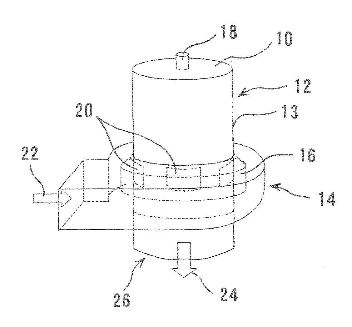
[0104] First, a combustion apparatus will be described with reference to FIGS. 4 and 5. The combustion apparatus shown in FIGS. 4 and 5 can be applied to general use mainly in boilers and industrial furnaces, and also in gas turbines. The combustion apparatus has an cylindrical container (hereinafter, simply referred to as a container) 12 with one end (close end) 10 which is closed, an inflow casing 14, a swirler 16, and a fuel nozzle 18 provided so as to extend through the upper end (close end) 10 of the container 12. A plurality of air inflow portions 20 are formed at common pitches on a side surface 13 of the container 12. Combustion air 22 flows through the air inflow portions 20 into the interior of the container 12, and inflow passages are formed by the air inflow portions 20, the inflow casing 14, and the swirler 16. The swirler 16, details of which will be described later, is formed so as to surround a perimeter of the side surface 13 of the container 12 including the air i...

second embodiment

[0111] In the combustion apparatus thus constructed combustion air 22 flowing through an inflow casing 14 flows into a swirler 16 and through the air inflow portions 20 into the container 112 upward in FIG. 7. By the swirler, details of which will be described later, the air 22 flowing into the container 112 forms a swirling flow 28 having a larger velocity component in a direction opposite to an outlet 26. Specifically, the air 22 forms a flow 28 having a velocity component in a direction of a central axis J of the cylindrical container 112 from the open end 26 to a close end 110 and a velocity component to swirl in a circumferential direction. Fuel is injected toward the air inflow portions (inflow passages) 20 with a velocity component in the direction of the central axis J from the close end 10 to the open end 26 and a velocity component directed radially outward.

[0112] The swirler 16 and the inflow casing 14 are substantially the same as those in a third embodiment described l...

third embodiment

[0117] In the example of the third embodiment shown in FIGS. 8 and 9, the swirler 16 will be described in detail with reference to FIGS. 10 to 12. As shown in FIG. 10, the swirler 16 is generally configured such that swirl vanes 54 for defecting a flow are disposed between the inner cylinder 50 and the outer cylinder 52 to form air introduction passages 56. Further, as shown in another example of FIG, 11, the swirler 16 may have a plurality of air introduction passages 56a opened in an annular member 58 for deflecting a flow. In this case, the shape, the opening area, and the number of the air introduction passages 56a may be set arbitrarily. Alternatively, as shown in still another example of FIG. 12 which achieves the same effects as the above swirler 16, air introduction passages 56b divided for each air inflow portion 20 in the connecting member 270 may be attached to the connecting member 270.

[0118] Further, in a structure shown in FIGS. 10 and 11, the swirler 16 may also serve...


PUM


Abstract

A combustion apparatus according to the present invention can positively control and generate burnt gas recirculation with a simple structure. The combustion apparatus has a cylindrical container (12) having a combustion chamber, a close end (10), and an open end (26), an inflow passages (20) for supplying combustion air into the combustion chamber in the cylindrical container (12), and a fuel nozzle (18) for supplying fuel into the combustion chamber in the cylindrical container (12). A flow (28) of air is formed so as to have a velocity component in a direction of a central axis (J) from the open end (26) to the close end (10) and a velocity component to swirl in a circumferential direction of said annular container (12). Fuel is injected so as to have a velocity component in the direction of the central axis (J) from the close end (10) to the open end (26) and a velocity component directed radially outward.

Description

TECHNICAL FIELD [0001] The present invention relates to a combustion apparatus and a combustion method, and more particularly to a combustion apparatus and a combustion method for supplying combustion air and fuel to a combustion chamber to mix and combust the combustion air and the fuel. BACKGROUND ART [0002] Regulation regarding air pollutants discharged from a combustion apparatus, particularly nitrogen oxide (NOx), becomes stricter and stricter. Thus, there has been demanded technology to reduce discharge of NOx. [0003] Nitrogen oxide (NOx) is generally classified according to its generation mechanism into three types: thermal NOx, prompt NOx, and fuel NOx. Thermal NOx is generated when nitrogen in air reacts with oxygen at a high temperature, and greatly depends on temperature. Prompt NOx is generated particularly in a flame of fuel-rich condition. Fuel NOx is generated while nitrogenous compounds contained in fuel are converted. [0004] Recently, clean fuel including no nitroge...

Claims


Application Information

Patent Timeline
IPC IPC(8): F02B17/00F23C7/00F23C6/04F23R3/10F23C99/00F23D11/00F23D11/12F23D11/40F23D14/02F23D14/22F23D17/00F23D99/00F23L1/00F23R3/14
CPCF23C6/045F23C7/002F23D17/002F23D11/404F23C2900/06041
Inventor AMANO, SHUNSUKEARAI, MASATAKA
Owner EBARA CORP
Why Eureka
Try Eureka