Impingement cooled heat sink with low pressure drop

a heat sink and heat exchanger technology, applied in the field of heat exchangers, can solve the problem of relatively low heat capacity of air, and achieve the effect of reducing the life of the pump, reducing the overall system pressure drop, and low overall system pressure drop

Inactive Publication Date: 2007-11-29
COOLIT SYSTEMS INC
View PDF14 Cites 95 Cited by
  • Summary
  • Abstract
  • Description
  • Claims
  • Application Information

AI Technical Summary

Benefits of technology

[0011]The liquid pump in a typical LCU is the most complex and expensive component of the system. The lifetime of a pump diminishes significantly as the overall system pressure drop increases. The disposition of the secondary and tertiary nozzles permits effective direction and circulation of the cooling fluid while maintaining a low overall system pressure drop over the assembly. By effectively metering the flow of the various nozzles, higher pressure drop can be concentrated over areas where the highest amount of heat flux exists. Further, the cold cooling fluid can be directed locally at regions of high heat load via the secondary and tertiary nozzles. If the entire amount of cooling fluid is discharged through a single nozzle, a very high pressure drop will be created. A moderate reduction in the total amount of fluid discharged through the lone nozzle results in a significant reduction of pressure drop. Hence, by apportioning the flow between primary, secondary and tertiary nozzles, the overall system pressure drop is reduced while maintaining a high heat transfer coefficient at regions of high heat flux.

Problems solved by technology

However, air has a relatively low heat capacity.

Method used


Image

  • Impingement cooled heat sink with low pressure drop
  • Impingement cooled heat sink with low pressure drop
  • Impingement cooled heat sink with low pressure drop

Examples


first embodiment

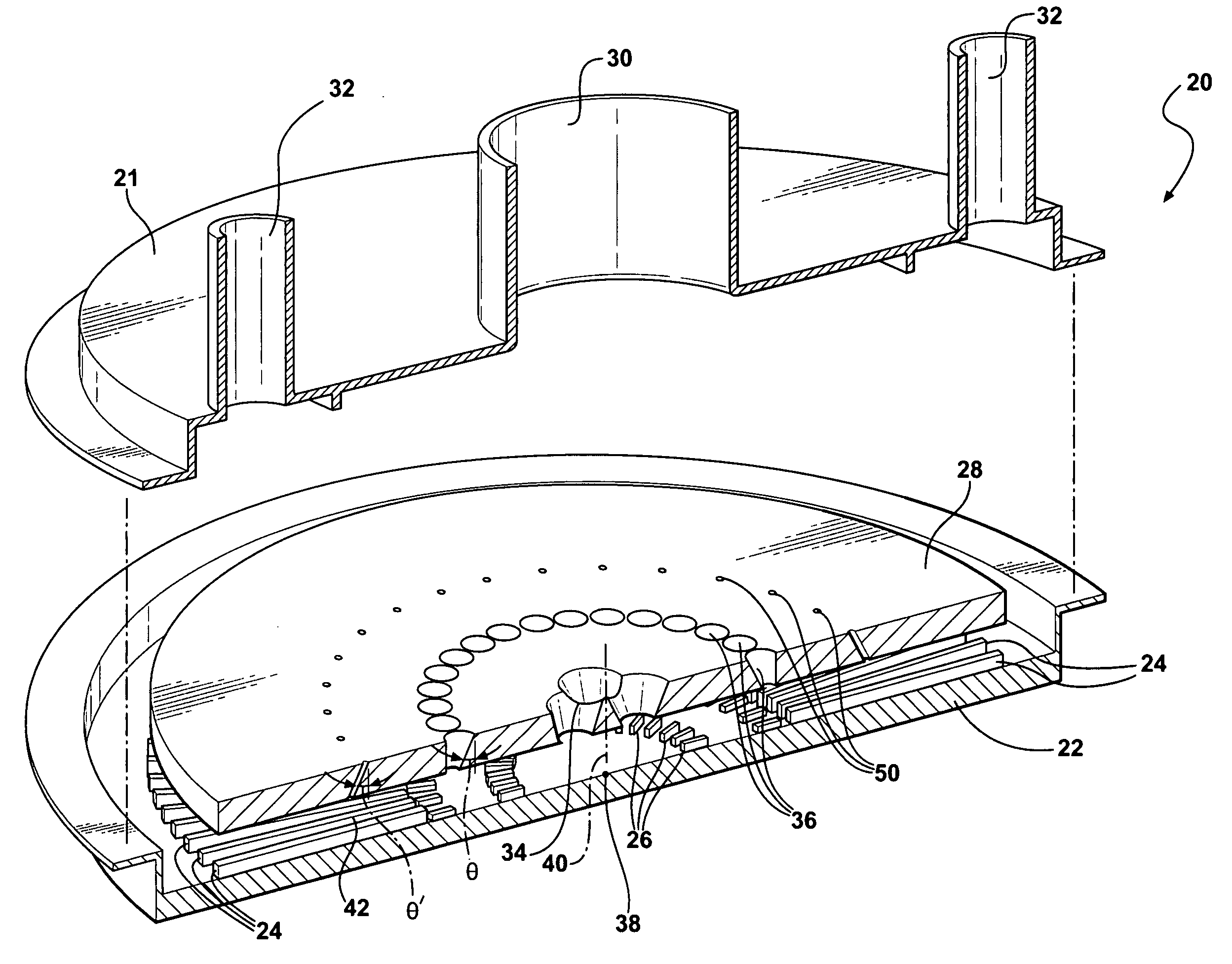
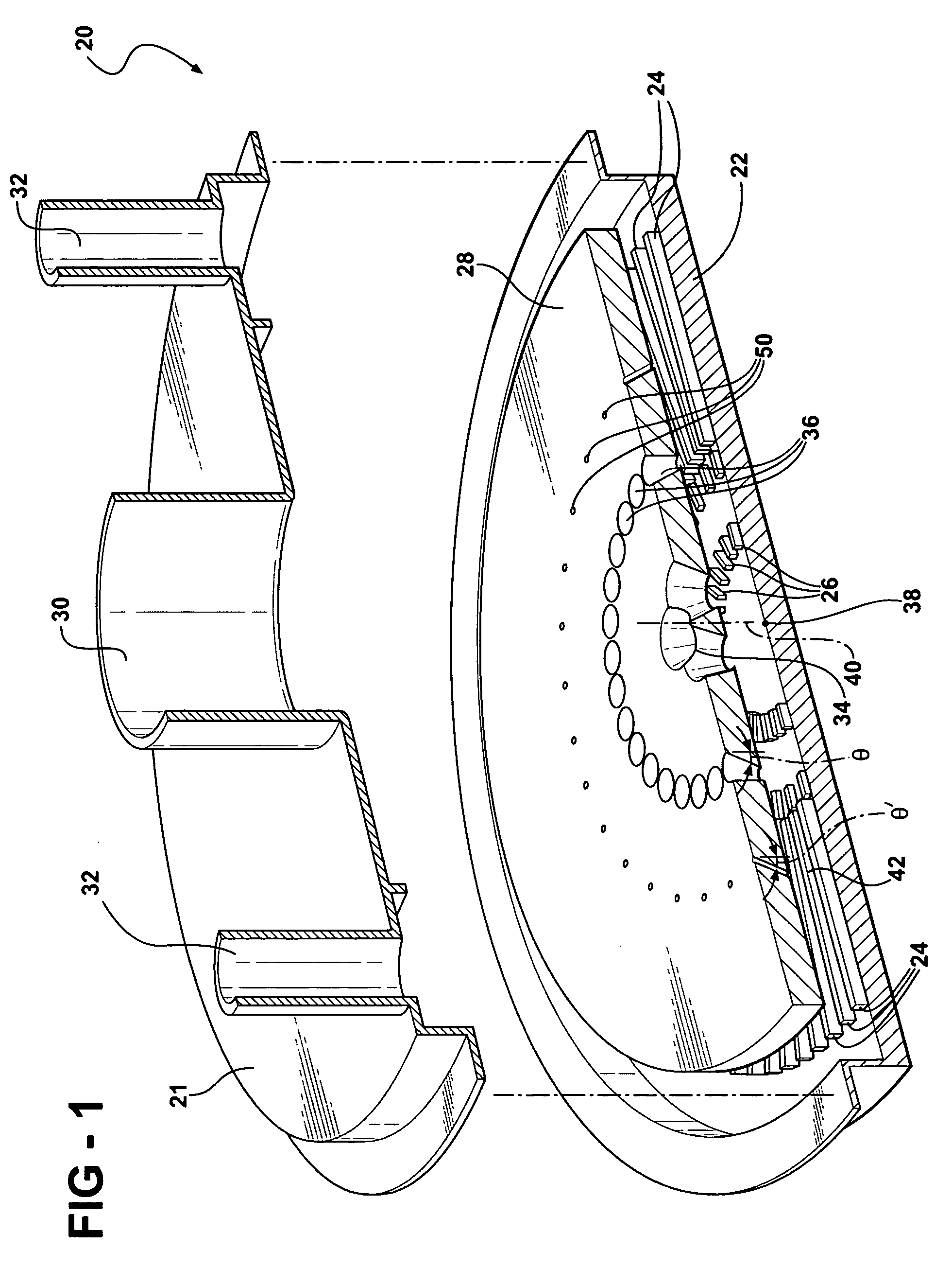
[0035]In the first embodiment shown in FIG. 1, the housing 20 and the nozzle plate 28 are circular in shape. The inlet 30 enters the housing 20 at the center 38 of the housing 20. Two outlets 32 are disposed across from each other on opposite sides of the circular housing 20 with the inlet 30 equidistant from each of the outlets 32. In other words, the inlet 30 and both outlets 32 are positioned along a single line with the inlet 30 being the midpoint and the outlets 32 being the endpoints.

[0036]A plurality of low fins 26 extend radially from the center 38 and are spaced radially from the center 38 and radially outward of the center 38. Similarly, a plurality of high fins 24 extend radially from the center 38 and radially outward of the center 38. The high fins 24 and low fins 26 are aligned outwardly from the center 38 and are spaced from the center 38 such that the low fins 26 are closer to the center 38 than the high fins 24. The nozzle plate 28 extends across the center 38 of th...

second embodiment

[0039]In the second embodiment shown in FIG. 3, the housing 20 and the nozzle plate 28 are rectangular in shape. The inlet 30 enters the housing 20 at the center 38 of the housing 20. Two outlets 32 are disposed across from each other on opposite sides of the rectangular housing 20. The nozzle plate 28 extends across the center 38 of the housing 20 and forms a fluid chamber 44 and a fin chamber 42, both rectangular in shape. The primary nozzle 34 is disposed at the center 38 of the nozzle plate 28. The primary nozzle 34 is elongated and defines an elongated slot 52. The primary nozzle 34 extends through the center axis 40 of the nozzle plate 28 and into the fin chamber 42. Alternatively, the elongated nozzle can comprise an array of nozzles 54 with each nozzle defining a conical bore.

[0040]The primary nozzle 34 in the second embodiment includes converging side walls 56 and end walls 58 that extend from the inlet 30 and through the nozzle plate 28. Additionally, the primary nozzle 34...


PUM


Abstract

Two embodiments of a heat exchanger assembly for cooling an electronic device are shown respectively in FIGS. 1 and 3 and each comprises a housing, a plurality of high fins, a plurality of low fins, a nozzle plate, an inlet, at least one outlet, a primary nozzle, and a plurality of secondary nozzles. In the first embodiment shown in FIG. 1, the housing and the nozzle plate are circular in shape. In the second embodiment shown in FIG. 3, the housing and the nozzle plate are rectangular in shape. Both embodiments include a plurality of secondary nozzles that are aligned outwardly of the primary nozzle and the center axis of the nozzle plate. The secondary nozzles direct the flow of the cooling liquid outwardly of the primary nozzle from the center thus creating an overall system pressure drop lower than that of other assemblies without a plurality of secondary nozzles.

Description

BACKGROUND OF THE INVENTION[0001]1. Field of the Invention[0002]The present invention relates to a heat exchanger for cooling an electronic device.[0003]2. Description of the Prior Art[0004]Electronic devices typically generate a high concentration of heat in the power density range of 5 to 35 W / cm2. Accordingly, research activities have focused on developing more efficient cooling assemblies capable of dissipating the heat generated from such electronic devices while occupying minimal space.[0005]A forced air cooling assembly typically includes a heat exchanger and a heat sink and cools the electronic device by natural or forced convection cooling methods. The electronic device is attached to the heat sink and transfers the heat thereto. The heat exchanger typically uses air to directly remove the heat from the heat sink. However, air has a relatively low heat capacity. Such forced air cooling assemblies are suitable for removing heat from relatively low power heat sources with a p...

Claims


Application Information

Patent Timeline
Patent Type & Authority Applications(United States)
IPC IPC(8): H05K7/20
CPCH01L23/4336H01L2924/0002H01L2924/00
Inventor GHOSH, DEBASHISBHATTI, MOHINDER SINGH
Owner COOLIT SYSTEMS INC
Why Eureka
Try Eureka