

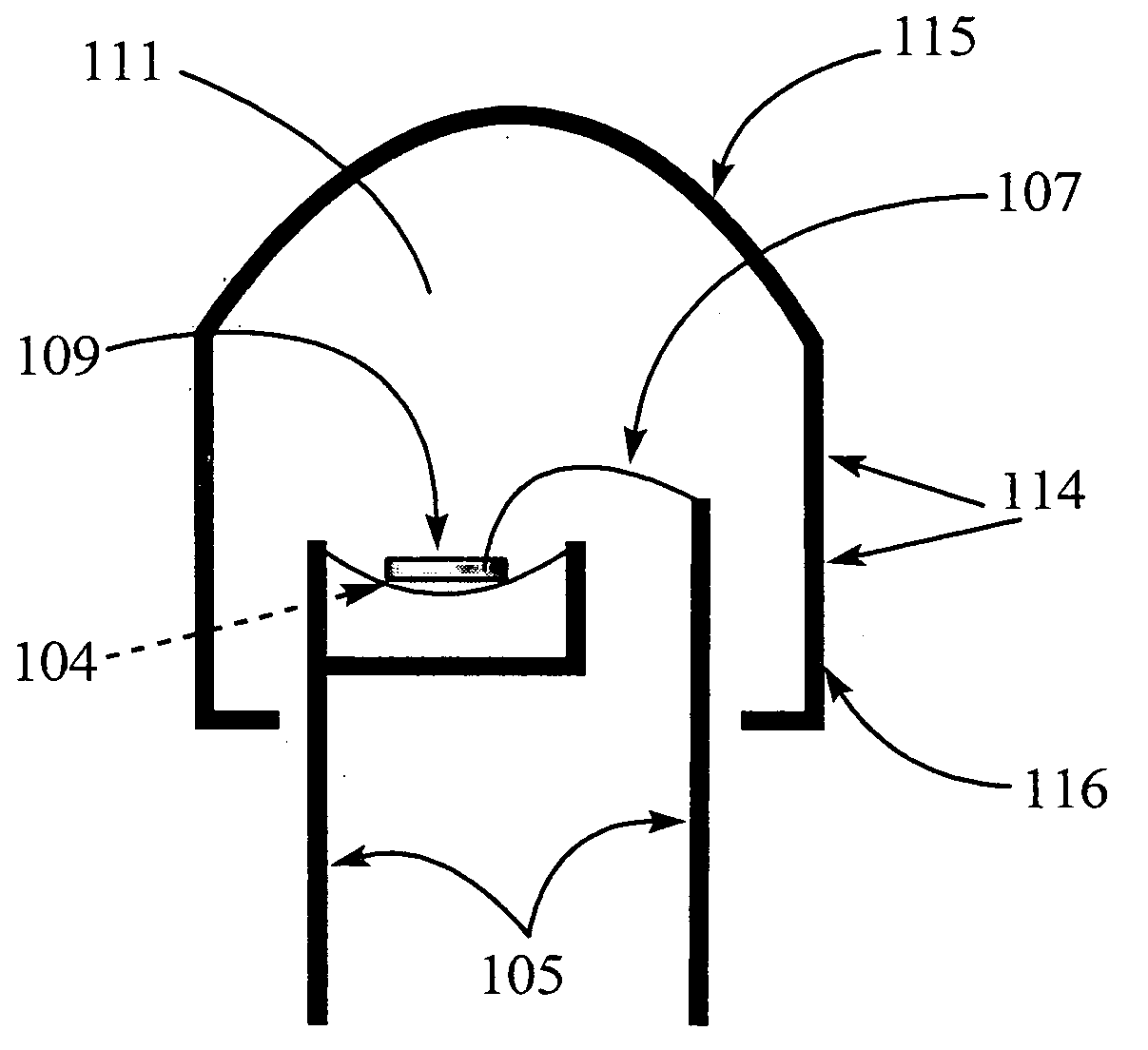
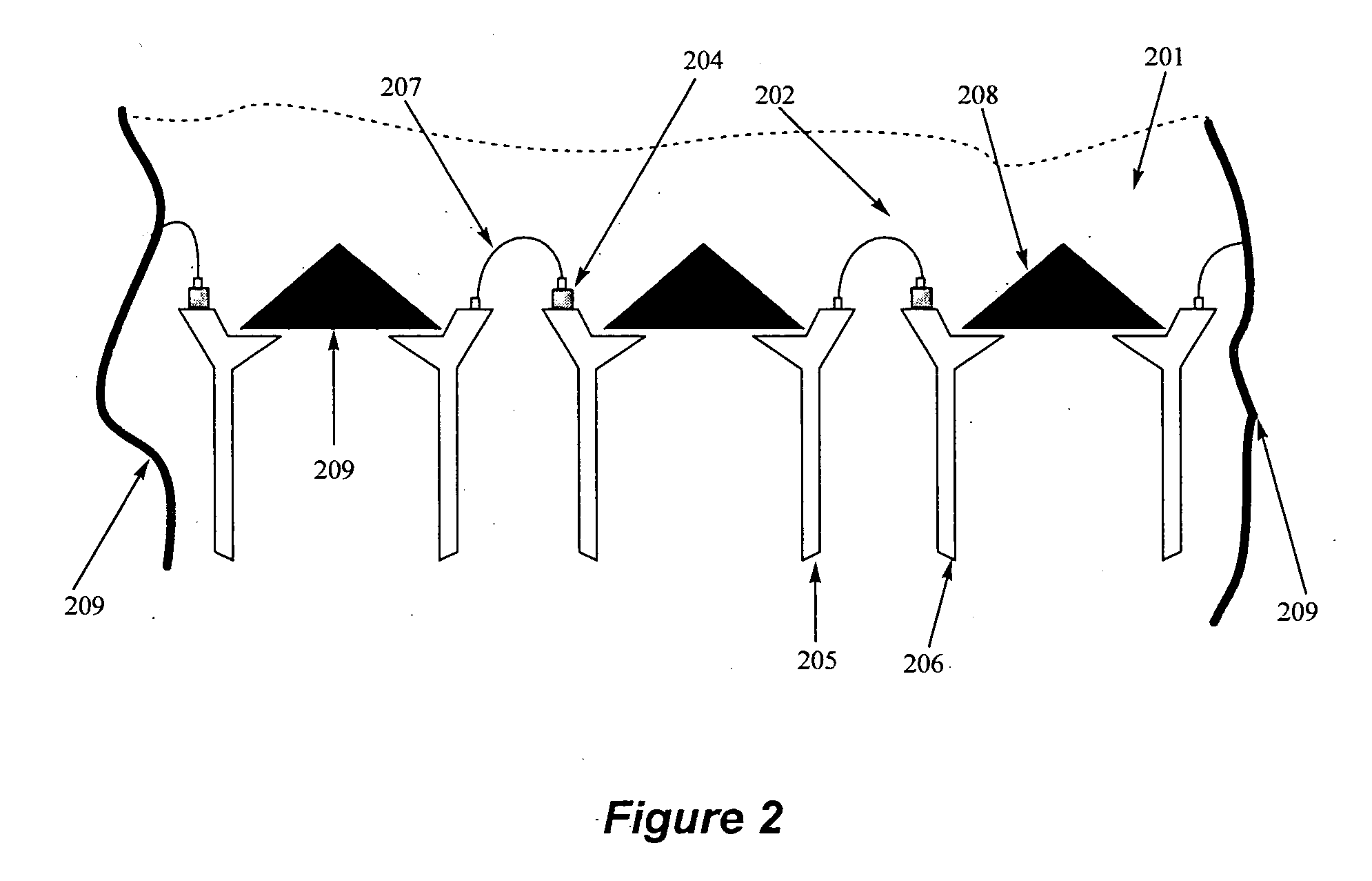
Optoelectronic device
a technology of optoelectronic devices and devices, applied in the direction of discharge tubes/lamp details, discharge tubes luminescent compositions, discharge tubes/lamp details, etc., can solve the problems of light scattering, decreased overall device efficiency, and less efficient pc-leds
- Summary
- Abstract
- Description
- Claims
- Application Information
AI Technical Summary
Problems solved by technology
Method used
Image

Examples
Embodiment Construction
[0014]The term refraction is defined herein as the bending of light as it passes between materials of different optical density. The term Refractive Index (n) of a material is defined as the ratio of the speed of light in vacuum (c) to the speed of light in that material (v).
[0015]It is to be understood herein, that if a “range” or “group” is mentioned with respect to a particular characteristic of the present disclosure, for example, percentage, chemical species, and temperature etc., it relates to and explicitly incorporates herein each and every specific member and combination of sub-ranges or sub-groups therein whatsoever. Thus, any specified range or group is to be understood as a shorthand way of referring to each and every member of a range or group individually as well as each and every possible sub-range or sub-group encompassed therein; and similarly with respect to any sub-ranges or sub-groups therein.
[0016]The present invention provides an optoelectronic device that comp...
PUM
 Abstract
Description
Claims
Application Information