Examination Apparatus, Fluoroscopy Apparatus, Examination Method, And Experimental Method

a fluoroscopy and apparatus technology, applied in the direction of fluorescence/phosphorescence, optical radiation measurement, instruments, etc., can solve the problems of reducing resolution, numerical aperture becomes significantly small, and difficulty in carrying out magnification within a wide range of magnification, so as to improve the examination accuracy, reduce the resolution of obtained images, and maintain the numerical aperture without significant reduction

Inactive Publication Date: 2007-11-29
OLYMPUS CORP
View PDF5 Cites 72 Cited by
  • Summary
  • Abstract
  • Description
  • Claims
  • Application Information

AI Technical Summary

Benefits of technology

[0059] According to the first and second aspects of the present invention, the objective lens can be switched in accordance with the change in magnifying power, and, at the same time, the image-forming lens can also be switched. In particular, by switching the objective lens to an objective lens having a low magnifying power and also switching the image-forming lens to a image-forming lens having a low magnifying power when examining a sp

Problems solved by technology

Therefore, it is difficult to carry out magnification within a wide range of magnifications.
In other words, since the same objective lens and image-forming lens are used from low magnification to high magnification, there is a problem in that, when the magnification is low, the numerical aperture be

Method used


Image

  • Examination Apparatus, Fluoroscopy Apparatus, Examination Method, And Experimental Method
  • Examination Apparatus, Fluoroscopy Apparatus, Examination Method, And Experimental Method
  • Examination Apparatus, Fluoroscopy Apparatus, Examination Method, And Experimental Method

Examples


first embodiment

[0105] A microscope examination apparatus according to a first embodiment will be described below with reference to FIGS. 1 to 15.

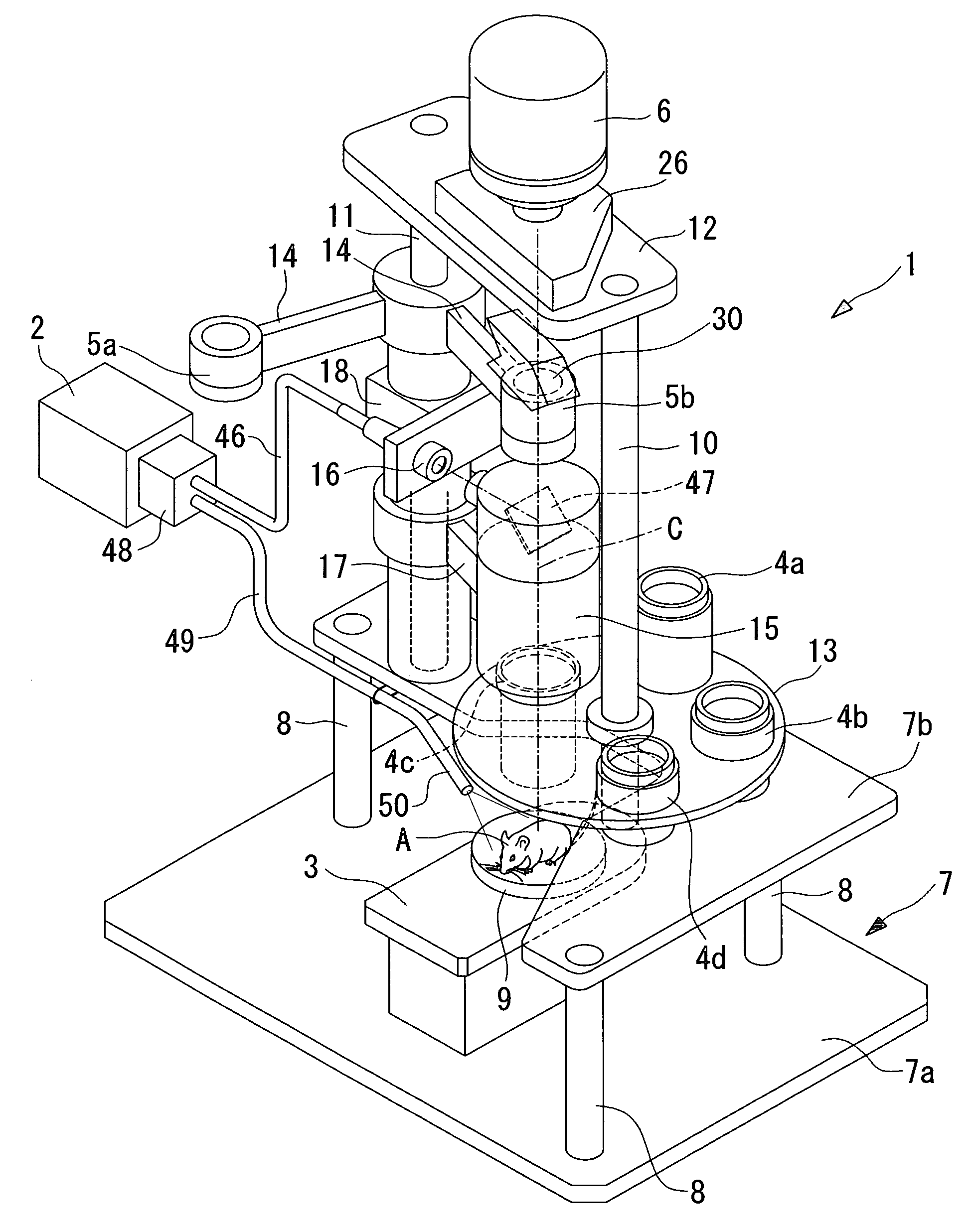
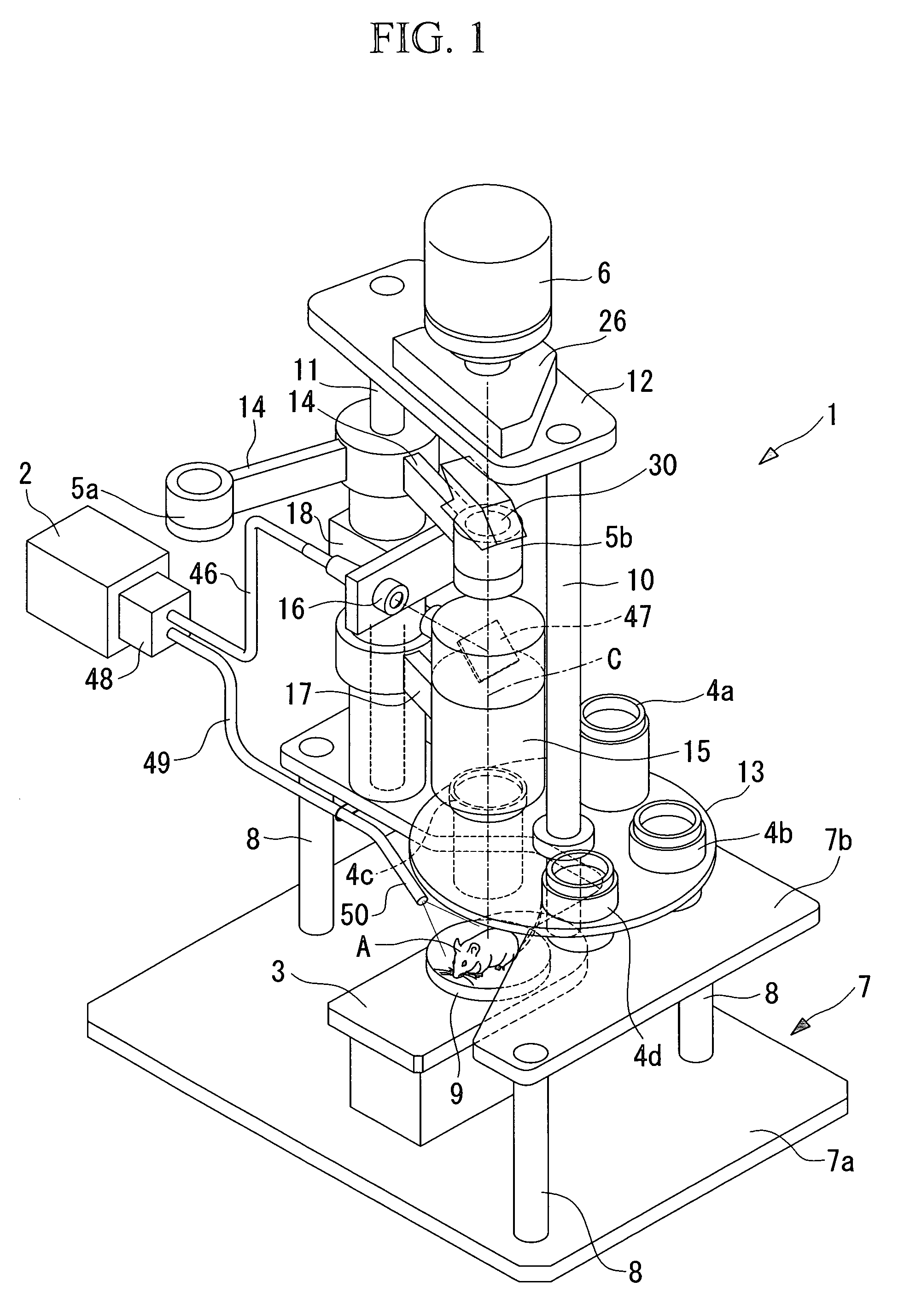
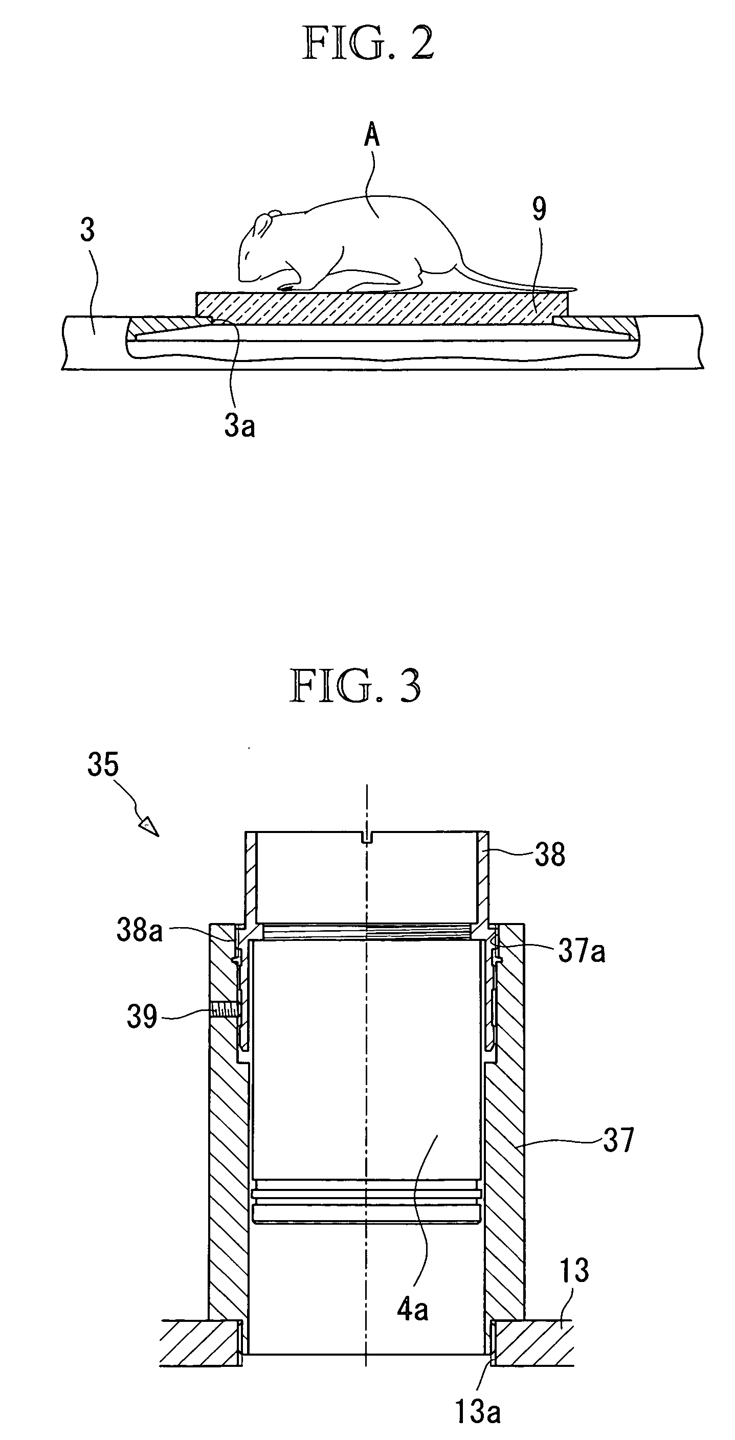
[0106] As shown in FIG. 1, a microscope examination apparatus 1 according to this embodiment includes a light source 2 configured to generate light emitted to a specimen A of a small laboratory animal or the like, such as a mouse, a stage 3 where the specimen A is disposed, objective lens units 4a to 4d configured to enlarge the return light from the specimen A, image-forming lens units 5a and 5b configured to enlarge and form a image of the specimen A enlarged by the objective lens units 4a to 4d, and a camera (image-capturing unit) 6 configured to capture the image of the specimen A formed by the image-forming lens units 5a and 5b.

[0107] The stage 3 is provided on a horizontally disposed base 7. The base 7 includes a first base 7a that is disposed on a horizontal mounting surface and a second base 7b horizontally disposed above the first base 7a, with...

second embodiment

[0154] Next, a microscope examination apparatus 60 according to a second embodiment of the present invention will be described with reference to FIG. 16. The description of this embodiment is simplified by representing the components that are the same as those in the microscope examination apparatus 1 according to the above-described first embodiment by the same reference numerals as those according to the first embodiment.

[0155] The microscope examination apparatus 60 according to this embodiment differs from the microscope examination apparatus 1 according to the first embodiment in that, as illustrated in FIG. 16, a turret 13, an arm 17, and a second turret 62 are attached to a single support stand 61 in a manner such that they are rotatable around the support stand 61.

[0156] More specifically, as illustrated in FIG. 16, the microscope examination apparatus 60 according to this embodiment includes a base 7 to which a stage 3 for holding a specimen A is fixed and the support sta...

third embodiment

[0159] Next, a microscope examination apparatus 70 according to a third embodiment will be described with reference to FIG. 17.

[0160] Also in this embodiment, components that are the same as those of the microscope examination apparatuses 1 and 60 according to the above-described embodiments will be represented by the same reference numerals to simplify the description.

[0161] The microscope examination apparatus 70 according to this embodiment is similar to the microscope examination apparatus 60 according to the second embodiment in that it includes a single support stand 61 fixed to a base 7.

[0162] As shown in FIG. 17, the microscope examination apparatus 70 includes a first lens group 71 that is a combination of an objective lens unit 4a and an image-forming lens unit 5a, and a second lens group 72 that is a combination of an objective lens unit 4d having a high magnifying power, a zooming mechanism 15, and an image-forming lens unit 5b. In the drawing, only one first lens gro...


PUM


Abstract

Even when the magnifying power is reduced, an image can be obtained at high resolution without significantly reducing the numerical aperture, and examination accuracy is improved. There is provided a microscope examination apparatus including a light source for emitting excitation light or illumination light to a specimen placed on a stage; an objective lens opposing the stage and capable of focusing fluorescence or reflected light from the specimen; an image-forming lens for forming an image of the specimen obtained by the objective lens; and an image-capturing unit for capturing the image of the specimen forming by the image-forming lens, wherein a plurality of the objective lenses having different magnifying powers is provided, and an objective-lens switching mechanism for switching among the objective lenses is provided, and wherein a plurality of the image-forming lenses having different magnifying powers is provided, and an image-forming-lens switching mechanism for switching among the image-forming lenses 5a and 5b is provided.

Description

TECHNICAL FIELD [0001] The present invention relates to examination apparatuses and fluoroscopy apparatuses for examining a living organism, organ, or tissue. BACKGROUND ART [0002] A conventionally known microscope examination apparatus is described in Patent Document 1. This microscope examination apparatus includes an objective lens disposed opposite to a specimen, an image-forming lens configured to form an enlarged image on an image-capturing unit, such as a CCD camera, and a magnifying relay lens detachably disposed between the objective lens and the image-forming lens and capable of continuously changing the magnifying power within a specific range of magnifications. [0003] According to this microscope examination apparatus, even when the objective lens and the image-forming lens are fixed and an afocal magnifying relay lens is detachably disposed therebetween, the confocal point on the image-capturing plane does not change and degradation of the image caused by the magnificat...

Claims


Application Information

Patent Timeline
IPC IPC(8): G01J3/30G02B21/36G01N21/64G02B21/00G02B21/24
CPCG02B21/248G01N21/6458
Inventor KAWANO, YOSHIHIROSHIMIZU, KEIJISUKEKAWA, MINORUMOCHIZUKI, TSUYOSHIHONDA, SUSUMUHAYASHI, KAZUHIRO
Owner OLYMPUS CORP
Why Eureka
Try Eureka