Network latency analysis packet and method

a network latency and packet technology, applied in the field of network latency measurement, can solve the problems of large amount of bandwidth, processing time, and memory for mib data storage, and achieve the effect of significantly reducing the bandwidth and processing required to assess packet transmission times and efficient methods of measuremen

Active Publication Date: 2007-11-29
AMERICAN TELEPHONE & TELEGRAPH CO
View PDF18 Cites 88 Cited by
  • Summary
  • Abstract
  • Description
  • Claims
  • Application Information

AI Technical Summary

Benefits of technology

[0005]At least some embodiments provide packets and/or methods for measuring network latency, potentially offering a more efficient method of measurement by comparison to existing methods. In at least some embodi

Problems solved by technology

This combined effort of querying multiple nodes in a network requires a signi

Method used


Image

  • Network latency analysis packet and method
  • Network latency analysis packet and method
  • Network latency analysis packet and method

Examples


Embodiment Construction

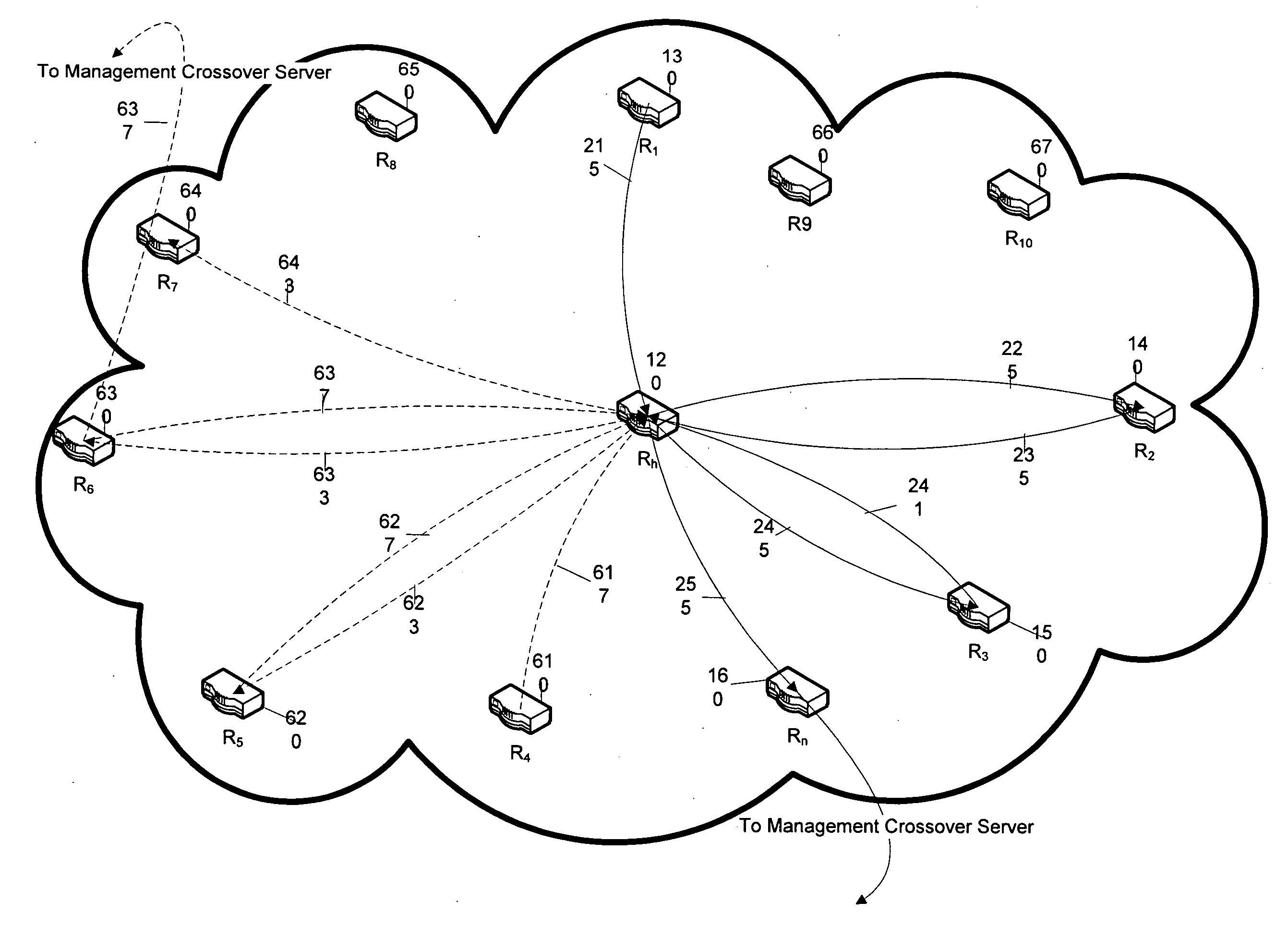
[0018]In at least some embodiments, delay between two or more nodes in a network can be determined. The network may be a local area network (LAN), wide area network (WAN), such as the Internet, or any other type of network connecting a plurality of computer devices. In some embodiments, delay is measured by sending at least one packet to various nodes in the network and returning to a point that may be outside the network to analyze the data in the at least one packet. In some embodiments, each node is identified by an IP address.

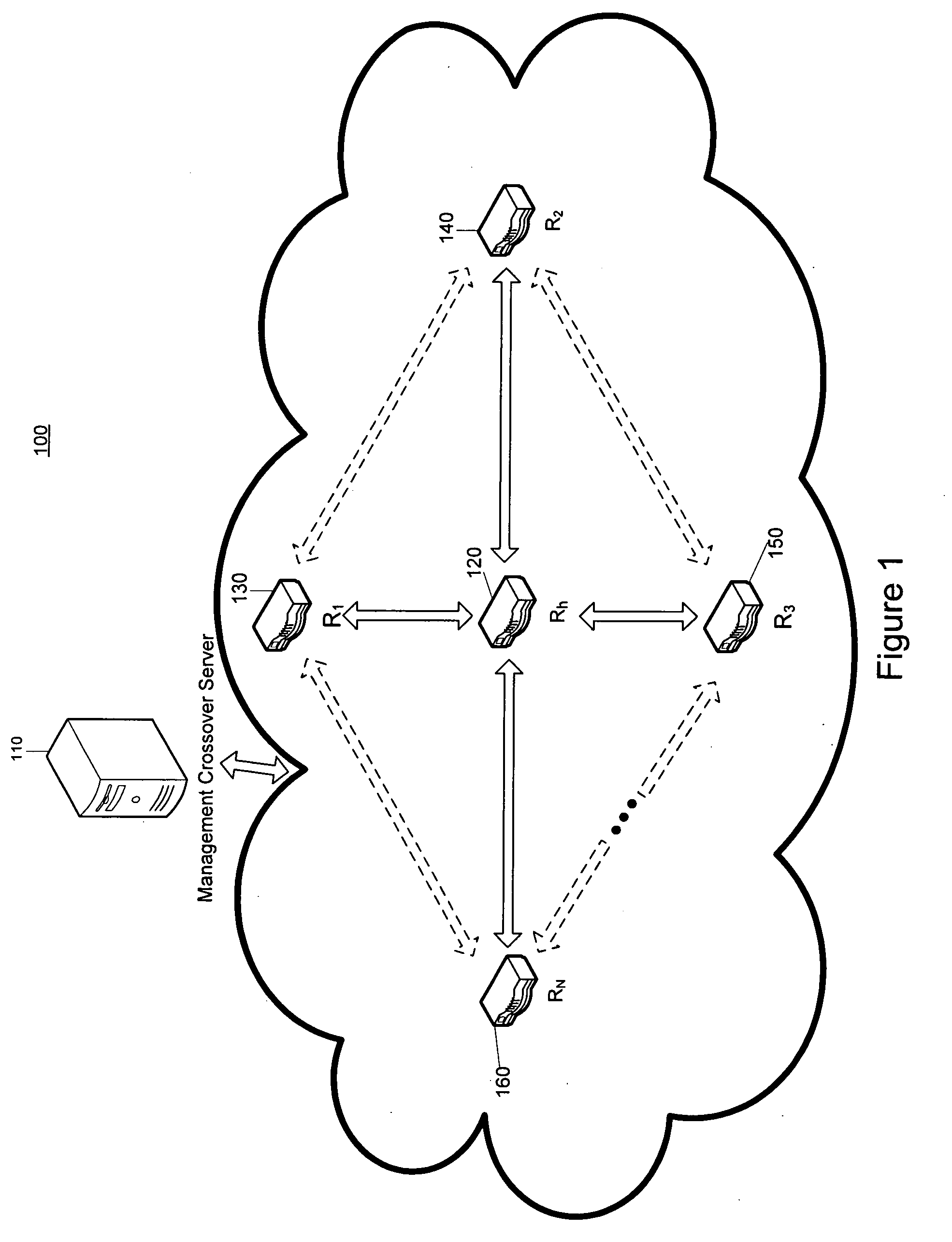
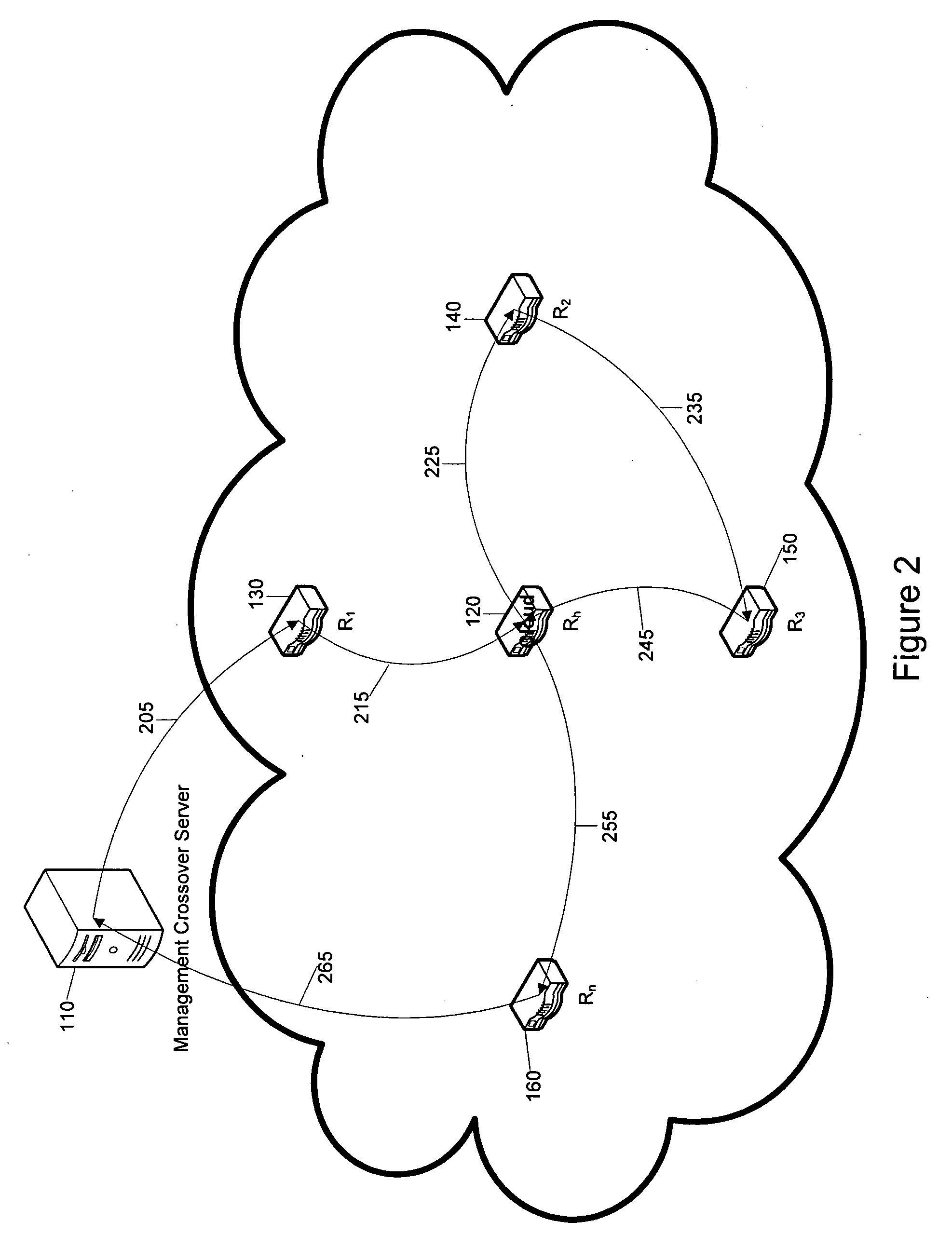
[0019]FIG. 1 illustrates one possible network configuration (100) having a spoke / hub network setup depicted by way of example. The following discussion of several embodiments should not be deemed limited to the depicted spoke / hub network configuration of FIG. 1 but rather encompasses other network configurations well known in the art. In the network configuration 100, spoke nodes R1 (130), R2 (140), R3 (150) and RN (160) (where N represents an arbitrary who...


PUM


Abstract

A packet and a method for analyzing network latency are disclosed. The disclosed systems and methods measure the latency between nodes in a network and do so while using less bandwidth and processing than traditional methods by using a packet to traverse a network and collect timestamps at various nodes so that the delay in transit time between nodes can be calculated when the packet returns to a server.

Description

FIELD OF THE INVENTION[0001]The present invention relates to the measurement of network latency in a packet switched network. More particularly, the invention provides packets and methods for traversing a network to calculate network latency.BACKGROUND OF THE INVENTION[0002]The time that it takes for a packet of data to travel between nodes in a packet switched network may be used to evaluate the health of a network. Each packet of data may take various routes through different nodes (such as routers or switches) to go from one endpoint to another. The route that is taken by one packet of data may be different than the route taken by another packet of data even if the two packets have the same origin and destination. This is done in order to optimize the use of bandwidth available in the network, minimize the transmission latency, and to increase the robustness of communication.[0003]Network providers offer Layer 3 network services, more commonly referred to as Virtual Private Netwo...

Claims


Application Information

Patent Timeline
IPC IPC(8): H04J1/16
CPCH04L12/2697H04L41/0213H04L43/50H04L43/0858H04L43/106H04L41/5009
Inventor RAUSCHER, FRANKWERNER, CARL E.
Owner AMERICAN TELEPHONE & TELEGRAPH CO
Why Eureka
Try Eureka