Method and system for tomographic imaging using fluorescent proteins

a technology of fluorescent proteins and tomography, applied in the field of optical tomography, can solve the problems of ineffective microscopy at the deeper imaging depth, inability to detect light,

Inactive Publication Date: 2007-11-29
THE GENERAL HOSPITAL CORP
View PDF7 Cites 42 Cited by
  • Summary
  • Abstract
  • Description
  • Claims
  • Application Information

AI Technical Summary

Problems solved by technology

Because microscopy requires substantially coherent light, this technique is only able to image to a small depth (e.g., less than l mm) into the specimen.
At deeper imaging depths, light is known to become diffuse, rendering microscopy ineffective at the deeper imaging depths.
However, reflectance fluorescence imaging has inherent limitations, since obtained images are a superposition of fluorescence signals from multiple depths, which tends to result in blurred images.
Furthermore, reflectance fluorescence imaging is not tomographic and does not retrieve depth information or allow absolute quantification of fluorescence activity.
This is due in part to non-linear light attenuation and propagation in biological tissues, which limits the applicability of reflectance fluorescence imaging to semi-quantitative imaging at depths of only a few millimeters.
Tomographic imaging using visible light, as provided by the conventional fluorescent proteins, is complicated by a relatively high absorption of visible light propagating in biological tissue, which results in significant attenuation.
However the advanced solutions to the transport equation are generally computationally expensive and become impractical for tomographic systems having a large number of excitation light sources, resulting in large data sets.
It is known that the optical switch generates energy losses.
It is known that a room temperature or moderately cooled CCD camera exhibits a relatively high level of dark (thermal) noise, which tends to limit the quality of resulting optical tomography images.

Method used


Image

  • Method and system for tomographic imaging using fluorescent proteins
  • Method and system for tomographic imaging using fluorescent proteins
  • Method and system for tomographic imaging using fluorescent proteins

Examples


Embodiment Construction

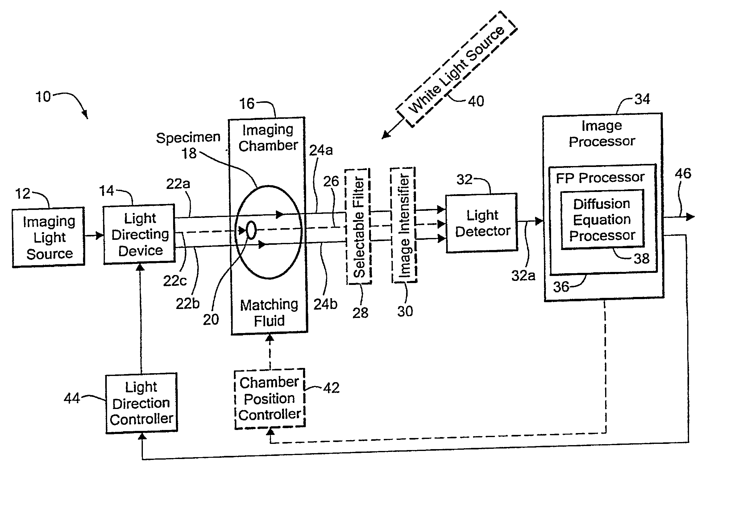
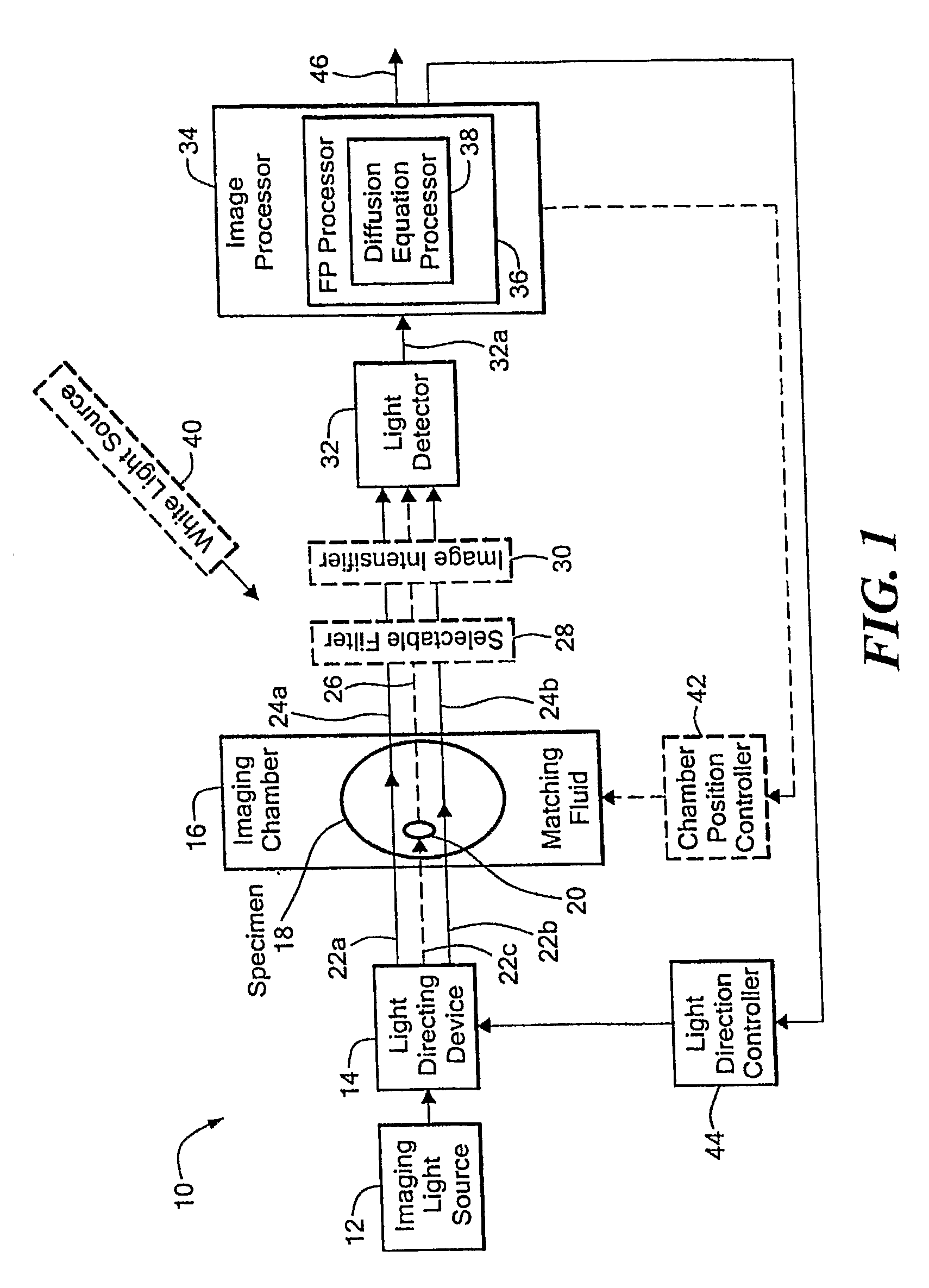
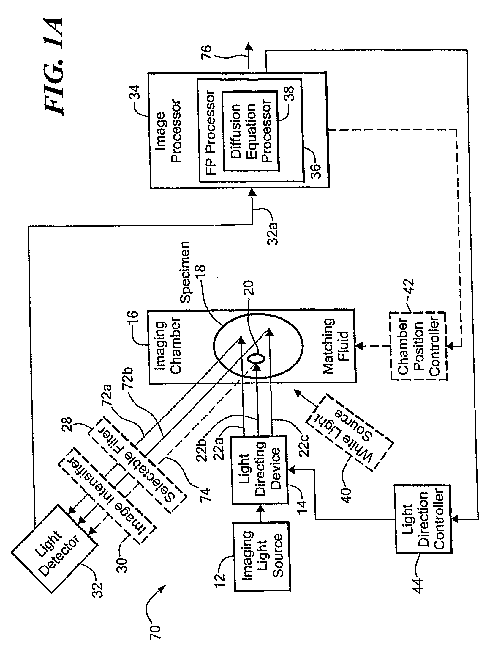
[0035] Before describing the imaging method and system, some introductory concepts and terminology are explained. As used herein, a “phantom” refers to a test object being imaged. A phantom is typically a manufactured article having diffuse light propagation characteristics similar to living tissue, for example, a piece of plastic. For another example, a phantom can be a vial having cells expressing the fluorescent proteins therein, i.e. a fluorescent marker.

[0036] As used herein, the term “apparent light sources” is used to describe projections of a single light source to a plurality of physical positions or angles, each providing an apparent light source.

[0037] As used herein, the term “excitation” light is used to describe light generated by an excitation light source, (for example, an apparent light source) that travels toward a specimen to be imaged, before entering the specimen. Once in the specimen, the light is referred to herein as “intrinsic” light. The intrinsic light i...


PUM


Abstract

A system for optical tomography includes an apparent light source adapted to project excitation light toward a specimen having fluorescent proteins therein, wherein the excitation light enters the specimen becoming intrinsic light within the specimen, wherein the intrinsic light is adapted to excite fluorescent light from the fluorescent proteins, and wherein the intrinsic light and the fluorescent light are diffuse. A method of optical tomography includes generating the excitation light with the apparent light source, wherein the intrinsic light and the fluorescent light are diffuse.

Description

FIELD OF THE INVENTION [0001] This invention relates generally to optical tomography and, more particularly, to a method and system for extracting quantitative, three-dimensional molecular and biological information from living specimens using fluorescent proteins. BACKGROUND OF THE INVENTION [0002] Fluorescent proteins (FPs) are important reporter molecules for different biomedical applications. In some existing applications, engineered FPs are detected by epi-fluorescence, conifocal (microscopy), or reflectance (whole animal) imaging. [0003] Epi-fluorescence, confocal microscopy depends on coherent (non-diffuse) light projected toward and reflected from a specimen. Because microscopy requires substantially coherent light, this technique is only able to image to a small depth (e.g., less than l mm) into the specimen. At deeper imaging depths, light is known to become diffuse, rendering microscopy ineffective at the deeper imaging depths. [0004] Reflectance fluorescence imaging has ...

Claims


Application Information

Patent Timeline
Patent Type & Authority Applications(United States)
IPC IPC(8): G06K9/00G01J1/58A61B5/00
CPCA61B5/0073A61B5/00
Inventor NTZIACHRISTOS, VASILISRIPOLL, JORGEZACHARAKIS, GIANNIS
Owner THE GENERAL HOSPITAL CORP
Why Eureka
Try Eureka