Eureka AIR delivers breakthrough ideas for toughest innovation challenges, trusted by R&D personnel around the world.

Medical laser wand

a laser wand and laser technology, applied in the field of medical laser wands, can solve the problems of limited use, limited level of therapeutic treatments involving diathermy, x-ray, microwave and electrical stimulation, and little or no benefit, and achieve the effect of less power

Inactive Publication Date: 2007-11-29
SEGAL KIM ROBIN
View PDF17 Cites 43 Cited by
  • Summary
  • Abstract
  • Description
  • Claims
  • Application Information

AI Technical Summary

Benefits of technology

[0014]It is therefore an object of this invention to provide a therapeutic medical laser operating in the region between near infrared and far infrared, which requires less power to operate than heretofore.

Problems solved by technology

While these techniques have shown some therapeutic benefit, their use has been somewhat limited because they generate excessive thermal energy which can damage tissue.
Consequently, the energy levels associated with therapeutic treatments involving diathermy, X-ray, microwave, and electrical stimulation have been limited to such low levels that little or no benefit has been obtained.
Thus, for a given tissue type, the laser light may propagate through the tissue substantially unattenuated, or may be almost entirely absorbed.
Although the foregoing laser systems perform well, they commonly generate large quantities of heat and require a number of lenses and mirrors to properly direct the laser light and, accordingly, are relatively large, unwieldy, and expensive.
Such systems, however, are still relatively large and unwieldy and, furthermore, are much more expensive to manufacture than a system which does not utilize fiber optic cable.
Moreover, the foregoing systems generate thermal effects which can damage living tissue, rather then provide therapeutic treatment to the tissue.

Method used


Image

  • Medical laser wand
  • Medical laser wand
  • Medical laser wand

Examples


Embodiment Construction

[0024]The following detailed description is of the best currently contemplated modes of carrying out the invention. The description is not to be taken in a limiting sense, but is made merely for the purpose of illustrating the general principles of the invention, since the scope of the invention is best defined by the appended claims.

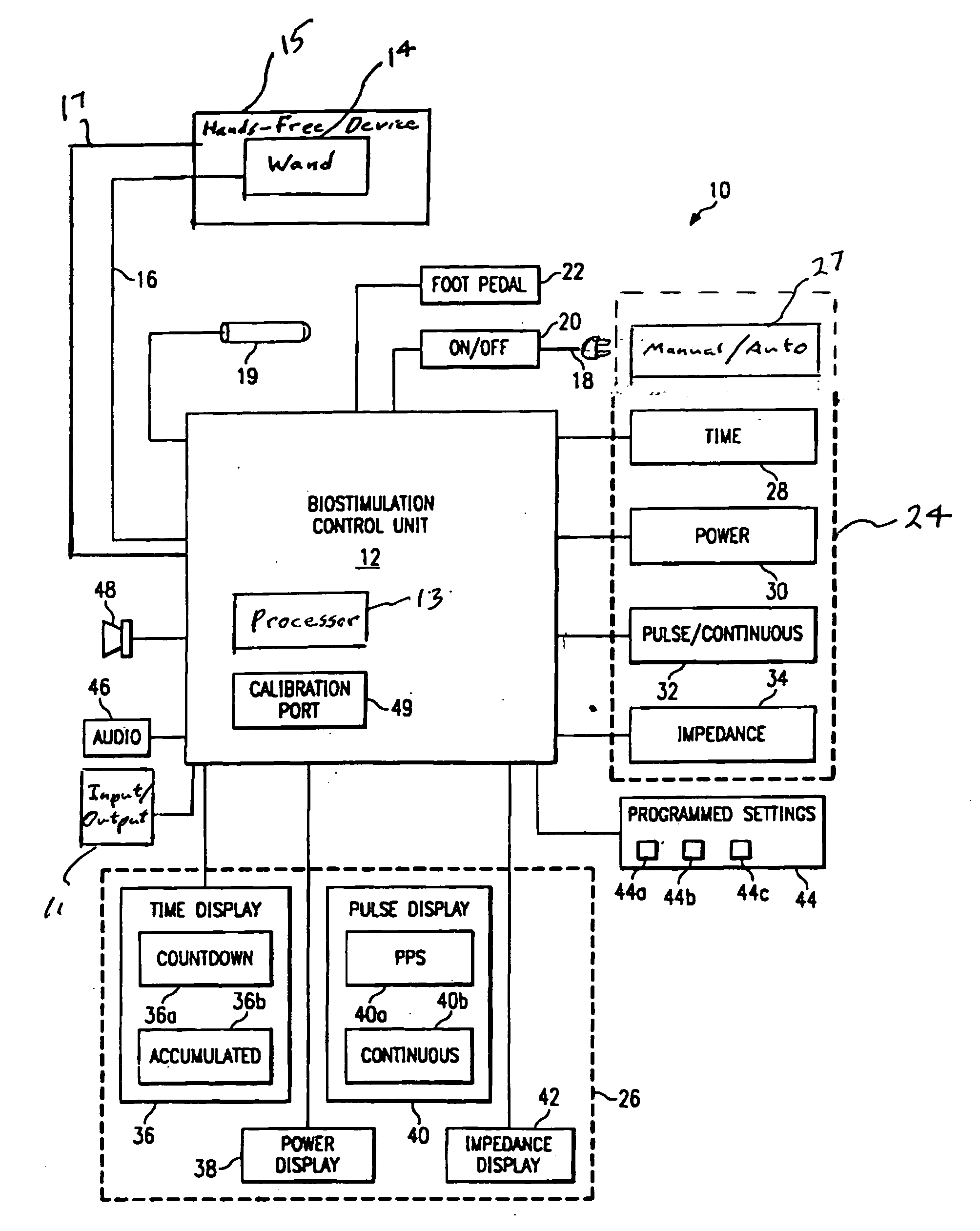
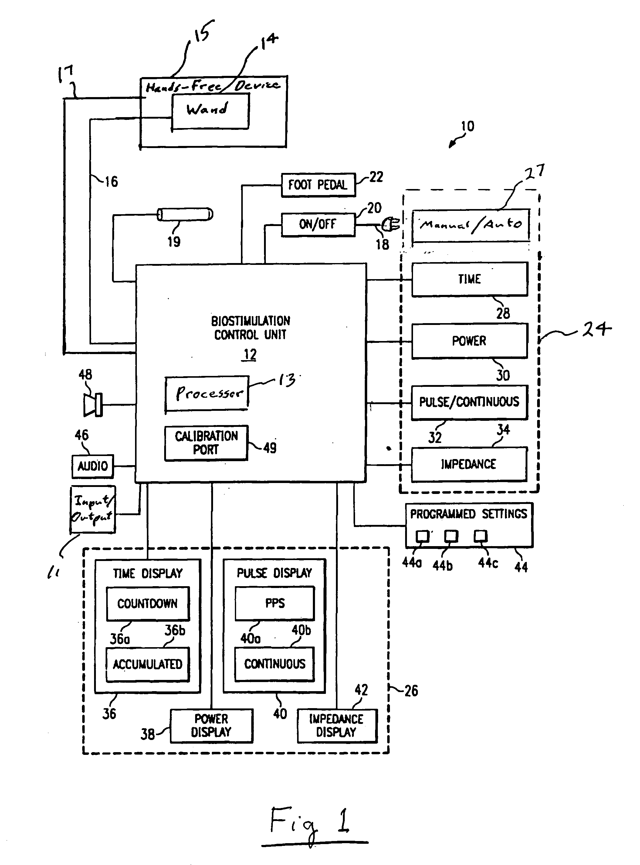
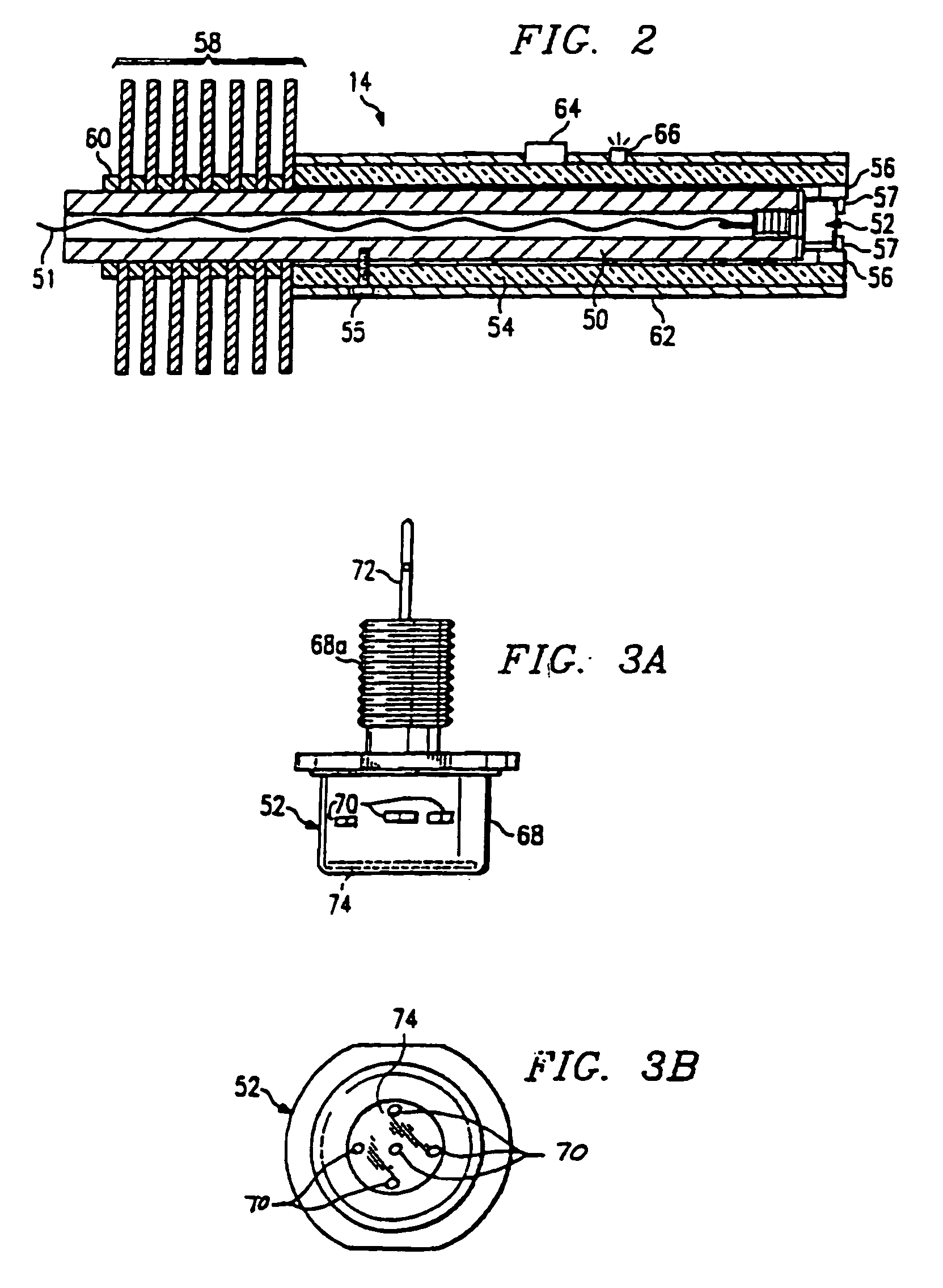
[0025]Broadly, the current invention includes systems, devices, and methods for the treatment of living biological tissue, either manually through use of a laser wand for stimulating soft, living tissue by diode laser irradiation, or automatically through use of a hands-free device that directs and controls the laser wand under programmatic control. The laser wand allows laser diodes located in an end of the wand to be moved over a given area of human skin surface. The automatic capability allows the laser wand to be moved in a regular manner, while providing a consistent energy output to the area being traversed, thus providing a more consistent result...


PUM


Abstract

A diode laser irradiation system for treating biological tissue of a subject without exposing the tissue to damaging thermal effects. The system includes a wand containing one or more diode lasers disposed for irradiating the tissue with coherent optical energy at a power output level of less than 1000 mw in aggregate at a wavelength in a range of from about 2500 nm to about 10,000 nm, and laser setting controls for operating the diode laser to achieve a rate of absorption and conversion to heat in the irradiated tissue in a range between a minimum rate sufficient to elevate the average temperature of the irradiated tissue to a level above the basal body temperature of the subject, and a maximum rate which is less than the rate at which the irradiated tissue is converted into a collagenous substance. The wand may be used manually or automatically in hands-free mode.

Description

CROSS-REFERENCES TO RELATED APPLICATIONS[0001]This application claims the benefit of U.S. Provisional Patent Application, Ser. No. 60 / 683,279, filed on May 27, 2005, the contents of which are hereby incorporated by reference in their entirety.BACKGROUND OF THE INVENTION[0002]The present invention generally relates to methods and devices for the treatment of living biological tissue, and more particularly to a hands-free laser wand for use in stimulating soft, living tissue by diode laser irradiation.[0003]Various non-surgical means have been employed in the therapeutic treatment of living tissue. Such techniques have included the application of ultrasonic energy, electrical stimulation, high frequency stimulation by diathermy, X-rays, and microwave irradiation. While these techniques have shown some therapeutic benefit, their use has been somewhat limited because they generate excessive thermal energy which can damage tissue. Consequently, the energy levels associated with therapeut...

Claims


Application Information

Patent Timeline
Patent Type & Authority Applications(United States)
IPC IPC(8): A61N5/06A61B18/18
CPCA61B2018/2085A61N2005/0651A61N2005/0644A61N5/06A61B2018/20351A61B2018/205547
Inventor SEGAL, KIM ROBIN
Owner SEGAL KIM ROBIN
Why Eureka
Eureka Blog
Learn More