Elastomer actuator and a method of making an actuator

a technology of actuators and elastomers, applied in the field of actuators, can solve the problems of reducing performance, reducing the performance, and changing the distance between the electrodes, and achieve the effect of improving performan

Inactive Publication Date: 2007-12-06
DANFOSS AS
View PDF41 Cites 21 Cited by
  • Summary
  • Abstract
  • Description
  • Claims
  • Application Information

AI Technical Summary

Benefits of technology

[0006] In accordance with the present invention, provision is made for an actuator made from an elastomer film and which facilitates an improved performance. Accordingly, the present invention in a first aspect provides an actuator comprising a tubular portion extending in a longitudinal direction, the tubular portion comprising a body of an elastomeric material arranged between two electrodes, wherein any line of symmetry extending between two opposite points on a periphery in a cross-section perpendicular to the longitudinal direction has a length which is different from any other such line of symmetry.
[0009] When an electrical potential is applied over the electrodes, the electrical force of attraction or repulsion forces the electrodes toward or away from each other whereby the elastomeric material is deformed. Due to the specific shape, it is achieved that the proportions of the tubular portion in directions perpendicular to the longitudinal direction are free to change during longitudinal expansion and contraction and therefore, the ability of the actuator to expand and constrict in the direction perpendicular to the longitudinal direction is improved when compared with actuators e.g. having a circular or a quadrangular cross-sectional shape, i.e. actuators exposing multiple axes of symmetry having equal length. Accordingly, a larger longitudinal expansion and contraction can be achieved.
[0012] The restriction and supporting of the deformation in the two directions may be achieved e.g. by forming corrugations in the electrodes and in the elastomeric bodies. The corrugations could extend mutually parallel in the first direction and thus support deformation in the second direction being perpendicular to the first direction. The corrugations could be formed during manufacturing of the elastomeric body in a moulding process. By vaporising a conductive material, e.g. gold, silver, copper, aluminium, or any similar conductive metal onto the body in a subsequent process, a very thin electrode may be formed onto the corrugations of the body. The electrode will effectively prevent deformation in the direction of the corrugations.
[0017] The element of the first type may further comprise a conductive terminal of a second type being electrically isolated from the electrode of the element. Correspondingly, the element of the second type may comprise a conductive terminal of a first type being electrically isolated from the electrode of the element. When the conductive terminals of the first type are in mutual electrical contact and the conductive terminals of the second type are in mutual electrical contact, e.g. when the elements are stacked, all terminals of the first type may be connected to one terminal of a power source at one connection point and all terminals of the second type may be connected to another terminal of the power source at another connection point. The terminals which are electrically isolated from the electrode of the element serve to bridge the electrical potential difference across the element between two adjacent elements.
[0019] In a specific embodiment of the invention, the rolled structure is formed by rolling the elements around an elastomer core. In order to reduce the impact of the core on the compliance of the rolled actuator, the elastomer core may be softer than the elastomer of the bodies of the actuator.

Problems solved by technology

As a result, the distance between the electrodes changes which leads to compression or tension of the elastomeric material which is thereby deformed.
It has, however, been found, that the rolled configuration of the elastomer film to a certain extent limits the ability of the film to deform and thus reduces the performance.

Method used


Image

  • Elastomer actuator and a method of making an actuator
  • Elastomer actuator and a method of making an actuator
  • Elastomer actuator and a method of making an actuator

Examples


Embodiment Construction

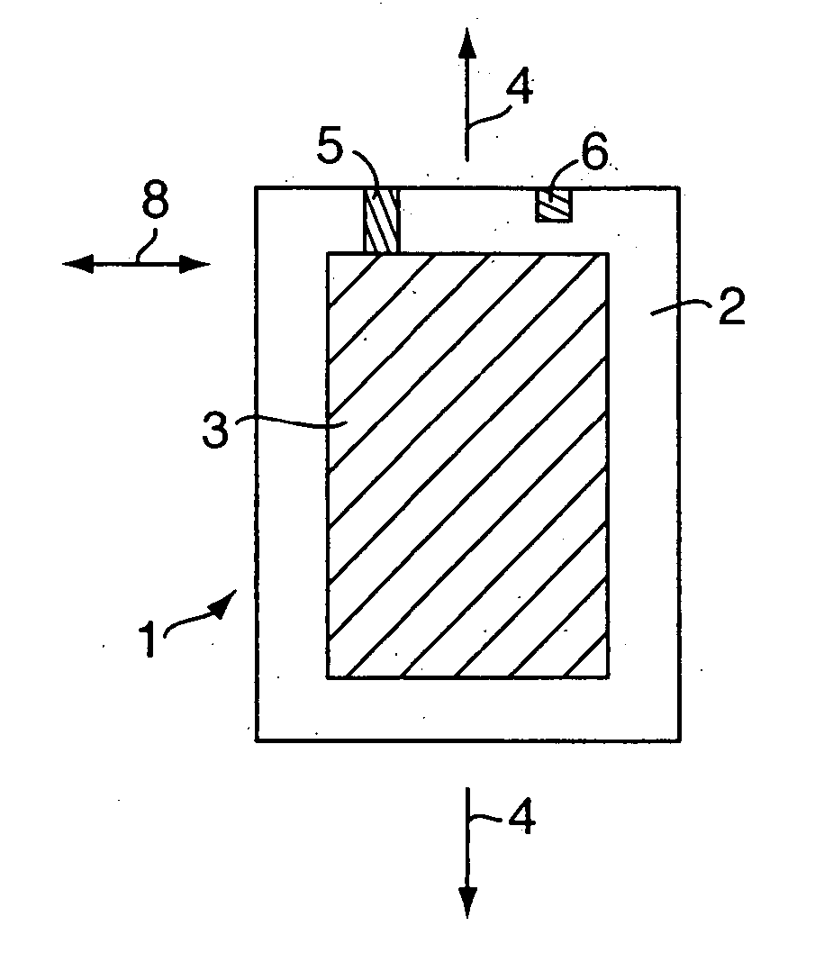
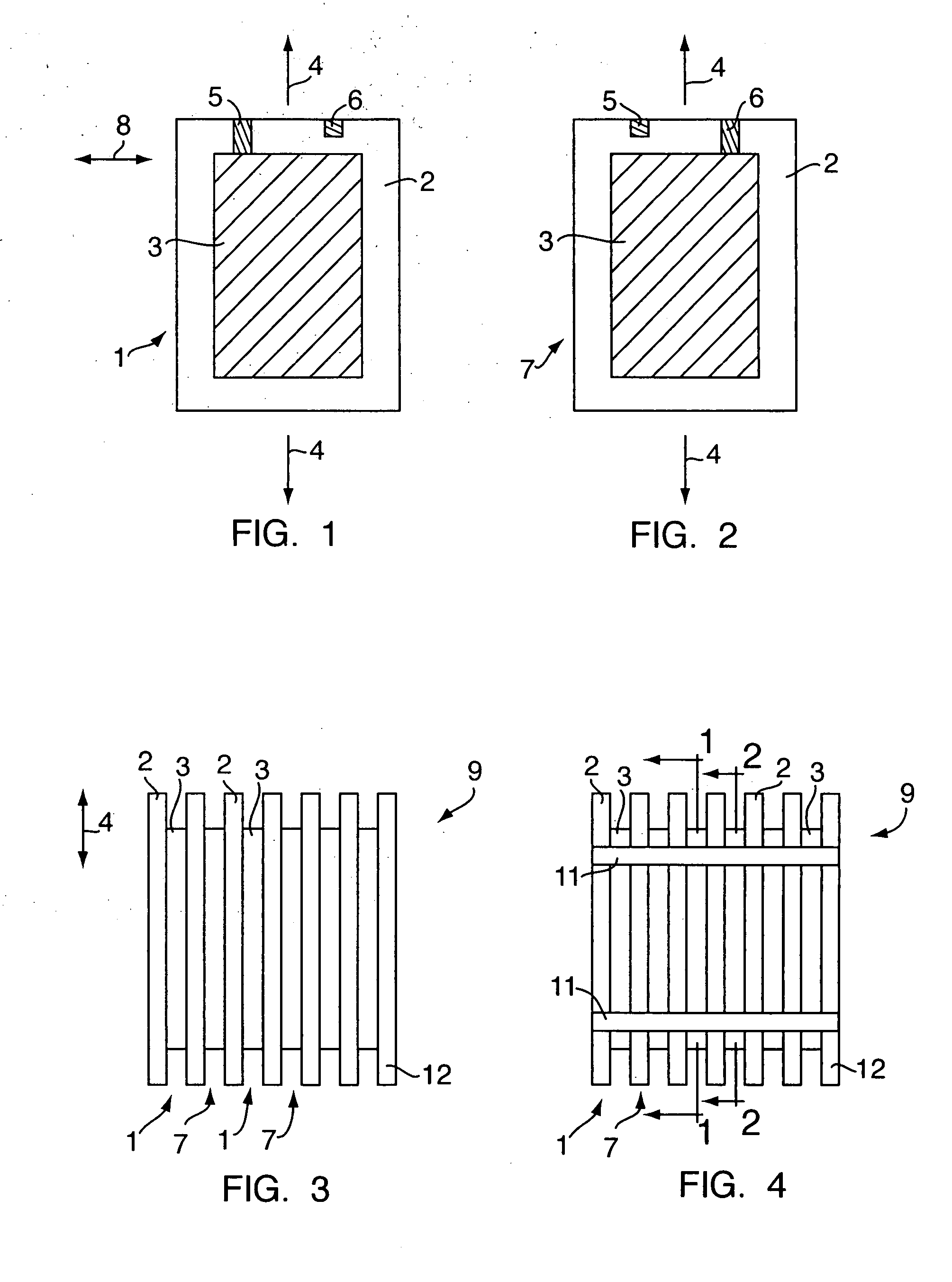
[0032]FIG. 1 shows a plate shaped element 1 for a laminated stack forming a sheet for an actuator. The element comprises a body 2 of an elastomeric material. The body 2 has a corrugated surface having a corrugated profile on one of its two surfaces, and an electrode 3 deposited on a large part of the corrugated surface. The electrode is deposited onto the surface of the body in a thickness of a few hundreds of Angstroms e.g. by vapour deposition of conductive particles onto the surface. The electrode could be made from gold, silver, or copper or from any other conductive material.

[0033] The corrugations of the body 2 are not shown in FIG. 1 but they should be understood to be corrugations, e.g. with a quasi-sinusoidal or a curved cross-sectional shape e.g. with a corrugation height from the top of a corrugation to the bottom of the corrugation in the order of ⅓-⅕ of the total thickness of the elastomer body. As an example, the corrugation height of a body having a total thickness o...


PUM

PropertyMeasurementUnit
sizeaaaaaaaaaa
thicknessaaaaaaaaaa
thicknessaaaaaaaaaa

Abstract

A tubular elastomer actuator with a shape in a cross-sectional view which shape exposes at most one single axis of symmetry of a specific length, e.g., an oval shape. The actuator could be made from a sheet made from a plurality of plate shaped elements which are laminated together and rolled. Each plate shaped element may have a corrugation that gives the element an anisotropic structure, and contains an electrode on only one surface. The actuator displacement is the result of shrinkage displacement of the plate shaped elements upon the application of electrical field across their thickness.

Description

CROSS REFERENCE TO RELATED APPLICATIONS [0001] This application is a Divisional Application of U.S. Ser. No. 10 / 528,503 entitled “An Elastomer Actuator and a Method of Making an Actuator” to Mohamed Y. Benslimane, et al. filed on Mar. 27, 2005 and claims the benefit of the filing date there of under U.S.C. §120. The present invention also claims priority from and incorporates by reference essential subject matter disclosed in international Patent Application No. PCT / DK2003 / 000603 filed on Sep. 18, 2003 and Danish Patent Application No. PA 2002 01380 filed on Sep. 20, 2002.FIELD OF THE INVENTION [0002] The present invention relates to an actuator, e.g. for use in robotic applications. BACKGROUND OF THE INVENTION [0003] Elastomer actuators with electrodes for deflecting an elastomeric material are known to facilitate large deformation in a relatively low electric field, e.g. when compared with alternative dielectric materials, e.g. piezoelectric materials including ceramics. The princ...

Claims


Application Information

Patent Timeline
Patent Type & Authority Applications(United States)
IPC IPC(8): H01L41/22H01L41/083H01L41/09H01L41/277H01L41/45H02N2/04
CPCH01L41/0836Y10T29/4902H01L41/277H01L41/45H02N1/002H01L41/27Y10T29/49171Y10T29/49146Y10T29/42Y10T29/4908Y10T29/43Y10T29/49176Y10T29/49226Y10T29/49117Y10T29/49007H01L41/0986H10N30/506H10N30/206H10N30/057H10N30/05H10N30/098
Inventor BENSLIMAND, MOHAMED YAHIAGRAVESEN, PETER
Owner DANFOSS AS
Why Eureka
Try Eureka