Premixing injector for gas turbine engines

a gas turbine engine and injector technology, applied in the direction of machines/engines, combustion types, lighting and heating apparatus, etc., can solve the problems of damage to the premixing injector, few designs have been made for hydrogen fuel operation, etc., to preserve the longevity of the premixing injector and improve the lifespan

a gas turbine engine and injector technology, applied in the direction of machines/engines, combustion types, lighting and heating apparatus, etc., can solve the problems of damage to the premixing injector, few designs have been made for hydrogen fuel operation, etc., to preserve the longevity of the premixing injector and improve the lifespan

US20070277528A1Inactive Publication Date: 2007-12-06VIRGINIA TECH INTPROP INC +1

Image

  • Premixing injector for gas turbine engines
  • Premixing injector for gas turbine engines
  • Premixing injector for gas turbine engines

Examples


example

[0072] The following Example is included solely for the purpose of providing a more complete and consistent understanding of the invention disclosed and claimed herein. The Example does not limit the scope of the invention in any fashion.

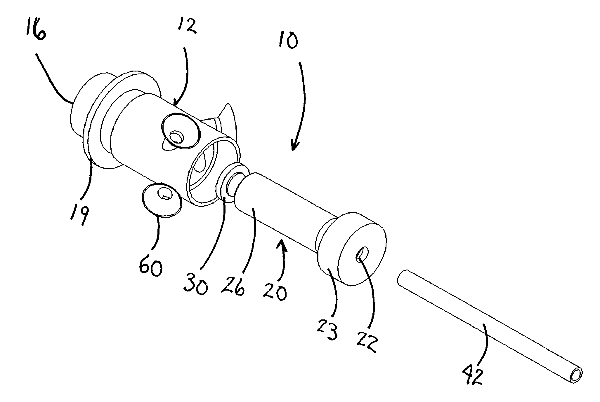
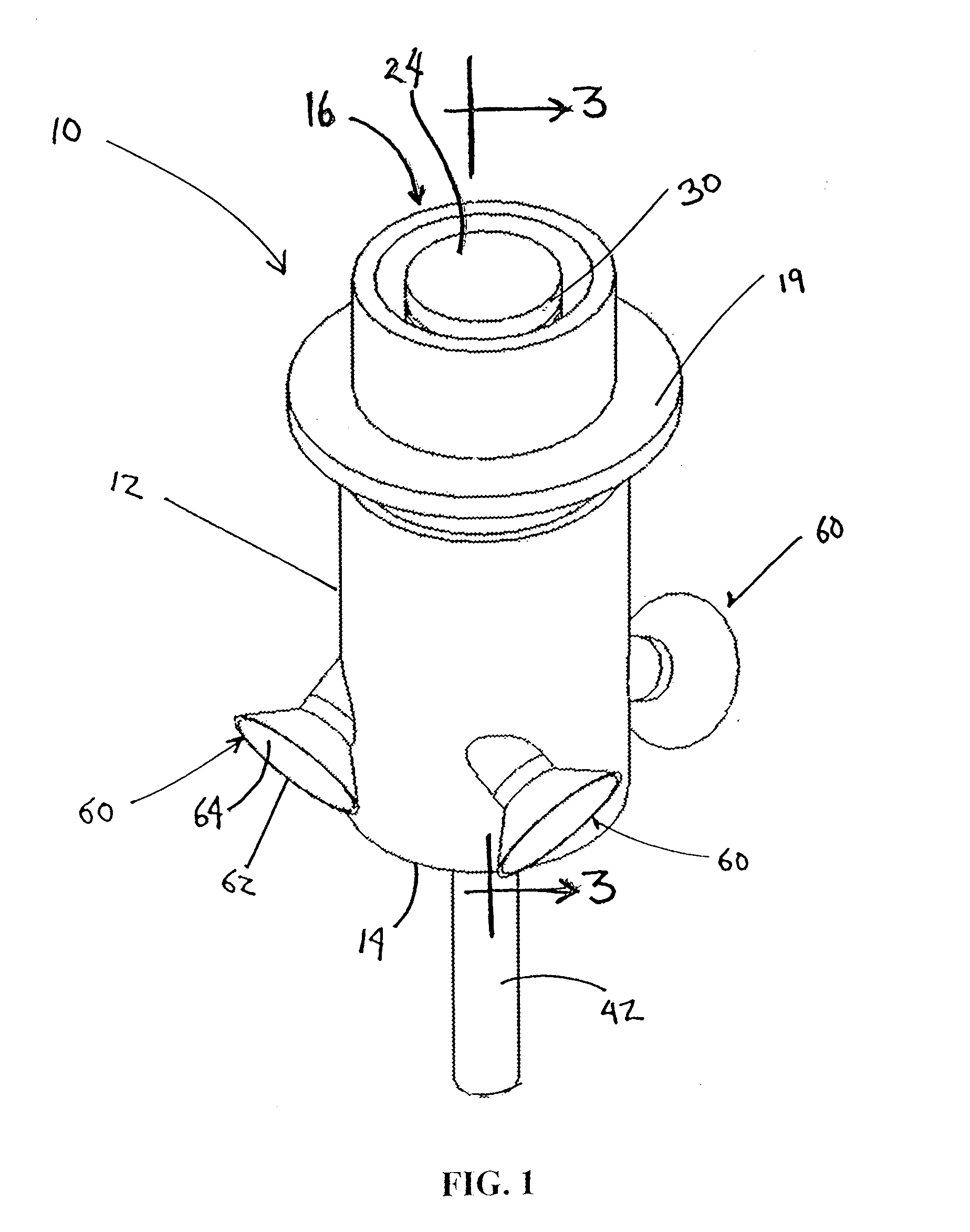
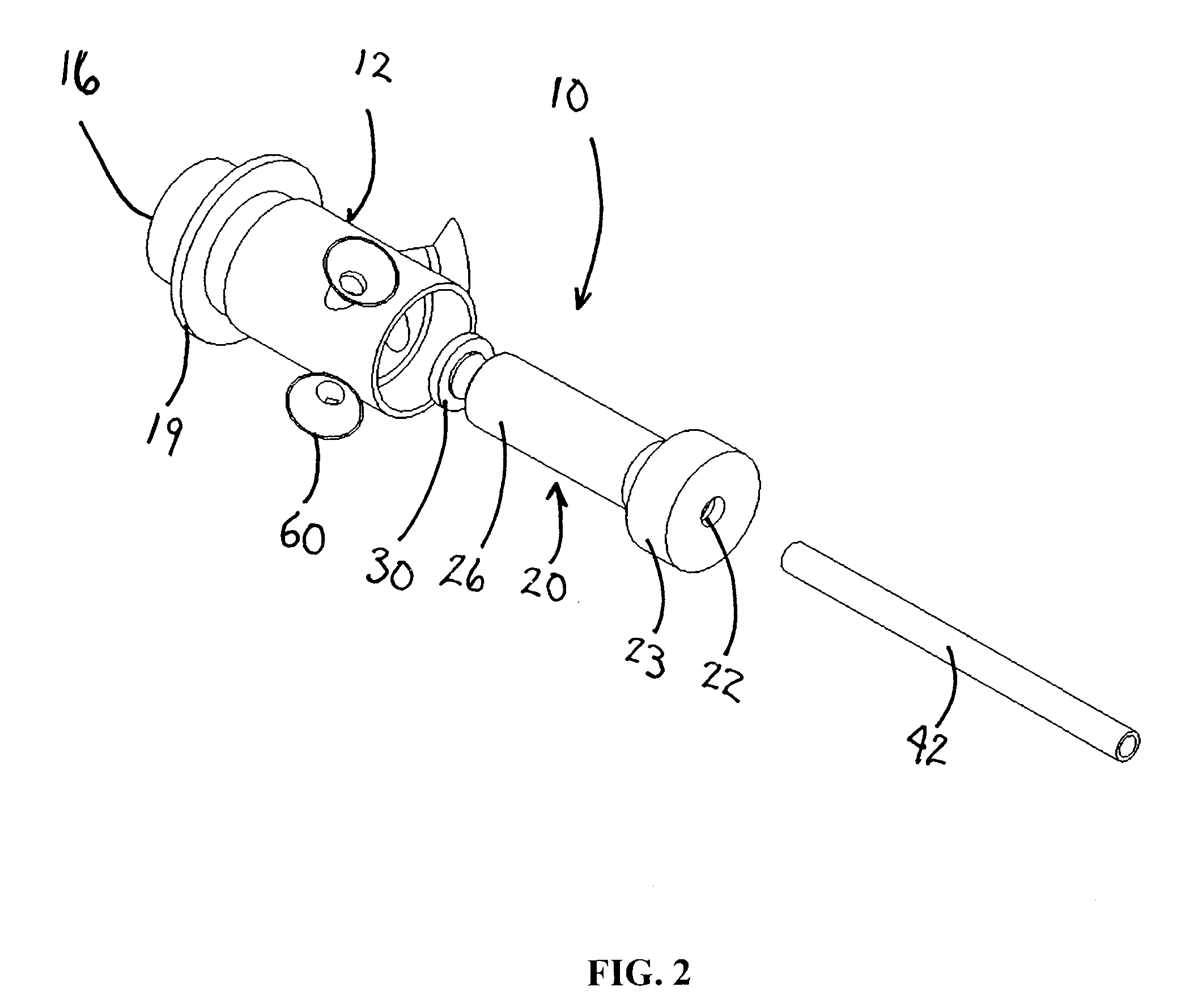
[0073] The design specifications for the premixing injector 10 enabled its use in a Pratt and Whitney PT6-20 turboprop engine. Since varying operating conditions of the engine (take off, cruise, and full power) are possible, there are multiple possible optimizations for the injector. The cruise condition was chosen for the optimization due to the normal high percentage of operational time at cruise. Table 1 shows the overall design constraints and the constraints per nozzle for the cruise condition of the engine. The fuel flow rate was determined by the equivalent energy flow rate based on lower heating value of hydrogen and kerosene. The number of premixing injectors 10 was chosen to ensure relative spatial uniformity in the engine liner. The equi...


PUM


Abstract

A premixing injector for use in gas turbine engines assists in the lean premixed injection of a gaseous fuel / air mixture into the combustor of a gas turbine. The premixing injector is designed to mix fuel and air at high velocities to eliminate the occurrence of flashback of the combustion flame from the reaction zone into the premixing injector. The premixing injector includes choked gas ports, which allow the fuel supply to be decoupled from any type of combustion instability which may arise in the combustor of the gas turbine and internal passages to provide regenerative cooling to the device.

Description

REFERENCE TO RELATED APPLICATION [0001] Priority is hereby claimed to provisional application Ser. No. 60 / 810,083, filed Jun. 1, 2006, which is incorporated herein by reference.FIELD OF THE INVENTION [0002] This disclosure relates to the field of combustion turbine engines. Specifically, the described devices can be used as a means of efficiently utilizing an alternative fuel, e.g., hydrogen, gas turbines while keeping the generation and emissions of nitrogen oxides to very low levels. More specifically, the present invention is a fuel / air premixing fuel injector or “premixing injector” which supports combustion in gas turbines with control of nitrogen oxide production. DESCRIPTION OF THE PRIOR ART [0003] Hydrogen use as a fuel in gas turbine engines has many benefits. In addition to being a renewable fuel, there are no carbon emissions from hydrogen combustion. Of available gas turbine fuels, hydrogen allows the widest range of combustible fuel-air mixtures, thus providing a superi...

Claims


Application Information

Patent Timeline
06 Dec 2007
Publication
US20070277528A1
IPC
F02C1/00
CPC
F23C2900/9901; F23D14/08; F23D14/58; F23R3/286; F23D14/82; F23D2209/10; F23D2900/14021; F23D14/64
Inventors
HOMITZ, JOSEPH; SYKES, DAVID M.