Acoustic Device And Method Of Making Acoustic Device

a technology of acoustic devices and acoustic output, which is applied in the direction of transducer diaphragms, electromechanical transducers, instruments, etc., can solve the problems of unbalanced panel modal behaviour and ineffective distribution mode methods, so as to prevent leakage of acoustic output and improve the performance of acoustic devices

Active Publication Date: 2007-12-06
TECTONIC AUDIO LABS INC
View PDF5 Cites 20 Cited by
  • Summary
  • Abstract
  • Description
  • Claims
  • Application Information

AI Technical Summary

Benefits of technology

[0067] A sealing member may be mounted in the aperture whereby the aperture is substantially acoustically sealed to prevent leakage of acoustic output. The ratio of the radius of the sealing to the outer radius of the diaphragm is an additional parameter which may be adjusted to achieve a desired acoustical response.
[0068] The acoustic device may be mounted in an enclosure and the acoustic properties of the enclosure may be selected to improve the performance of the acoustic device.

Problems solved by technology

This is due to the various masses and compliances now present unbalancing the panel's modal behaviour.
But this distributed mode method may not be so effective at the lower bending frequencies where modes are sparse and generally insufficient to construct a satisfactory frequency response.

Method used


Image

  • Acoustic Device And Method Of Making Acoustic Device
  • Acoustic Device And Method Of Making Acoustic Device
  • Acoustic Device And Method Of Making Acoustic Device

Examples


Embodiment Construction

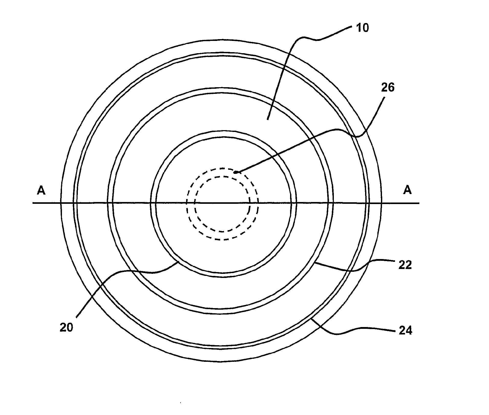
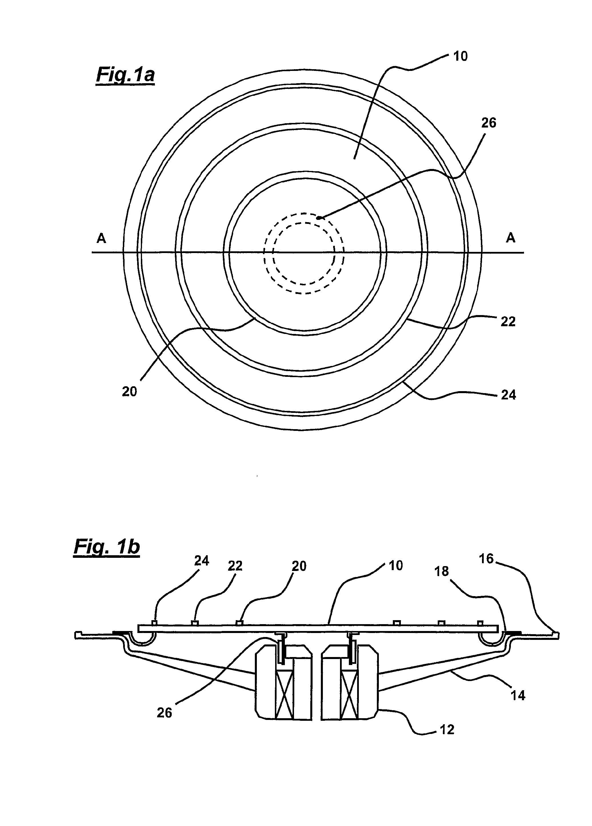
[0171]FIGS. 1a and 1b show a loudspeaker comprising a diaphragm in the form of a circular panel 10 and a transducer 12 having a voice coil 26 concentrically mounted to the panel 10. Three ring-shaped (or annular) masses 20,22,24 are concentrically mounted to the panel 10 using adhesive tape. The voice coil and masses are each located at annular positions which may be termed positions 1 to 4 with position 1 being the innermost location and position 4 the outermost.

[0172] The panel and transducer are supported in a circular chassis 14 which comprises a flange 16 to which the panel 10 is attached by a circular suspension 18. The flange 16 is spaced from and surrounds the periphery of panel 10 and the suspension 18 is attached at an annulus spaced from the periphery of the panel 10. In this way, the panel edge is free to move which is important since there is an anti-node at this location. Similarly, there are no masses located at the centre of the panel since there is also an anti-nod...


PUM


Abstract

An acoustic device comprising a diaphragm (10) having an area and having an operating frequency range and the diaphragm (10) being such that it has resonant modes in the operating frequency range, an electromechanical transducer having a drive part coupled to the diaphragm (10) and adapted to exchange energy with the diaphragm, and at least one mechanical impedance means (20,22,24) coupled to or integral with the diaphragm, the positioning and mass of the drive part (26) of the transducer and of the at least one mechanical impedance means (20,22,24) being such that the net transverse modal velocity over the area of the diaphragm (10) tends to zero. A method of making an acoustic device having a diaphragm having an area and having an operating frequency range which includes the piston-to-modal transition, comprising choosing the diaphragm parameters such that it has resonant modes in the operating frequency range, coupling a drive part of an electro-mechanical transducer to the diaphragm to exchange energy with the diaphragm, adding at least one mechanical impedance means to the diaphragm, and selecting the positioning and mass of the drive part of the transducer and the positioning and parameters of the at least one mechanical impedance means so that the net transverse modal velocity over the area tends to zero.

Description

TECHNICAL FIELD [0001] The invention relates to acoustic devices, such as loudspeakers and microphones, more particularly bending wave devices. BACKGROUND ART [0002] From first principles, a point force applied to a pistonic loudspeaker diaphragm will provide a naturally flat frequency response but a power response which falls at higher frequencies. This is due to the radiation coupling changing as the radiated wavelength becomes comparable with the length l of the diaphragm, or the half diameter or radius a for a circular diaphragm, i.e. where ka is greater than 2 or kl is greater than 4 (k is the wave number frequency). However for a theoretical, free mounted bending wave panel speaker, a pure force, i.e. mass-less point drive, will provide both flat sound pressure and flat sound power with frequency. [0003] A practical bending wave panel will however be supported on a suspension, and have an exciter with a complex driving point impedance including a mass. Such an object will demo...

Claims


Application Information

Patent Timeline
Patent Type & Authority Applications(United States)
IPC IPC(8): H04R7/04H04R7/10
CPCH04R7/10H04R7/045H04R7/00H04R7/04H04R31/00
Inventor BANK, GRAHAMHARRIS, NEIL
Owner TECTONIC AUDIO LABS INC
Why Eureka
Try Eureka