Multipole lens and method of fabricating same

Inactive Publication Date: 2007-12-06
JEOL LTD
View PDF11 Cites 13 Cited by
  • Summary
  • Abstract
  • Description
  • Claims
  • Application Information

AI Technical Summary

Benefits of technology

[0023] It is an object of the present invention to provide a multipole lens that can be machined at improved a

Problems solved by technology

However, machining of a circular assembly reference using wire electric discharge machining is impossible to perform because of interference with the polar elements on the atmospheric side.
When the workpiece is reinstalled on the machine tool for plural machining steps, machining errors will be accumulated.
Because of the reasons described so far, in the prior-art technique, the step for machining an assembly reference cannot be made common with the s

Method used


Image

  • Multipole lens and method of fabricating same
  • Multipole lens and method of fabricating same
  • Multipole lens and method of fabricating same

Examples


Example

Embodiment 1

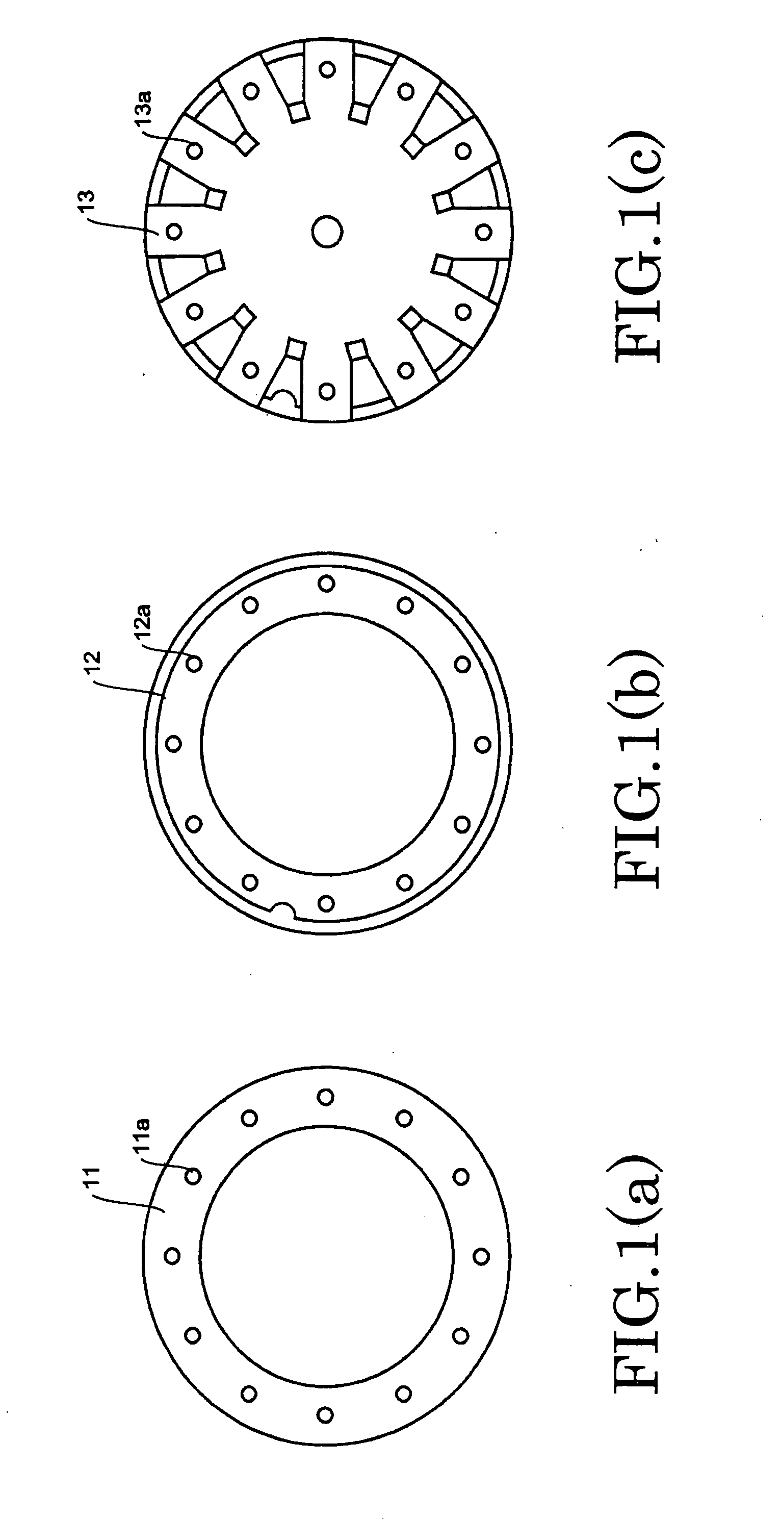
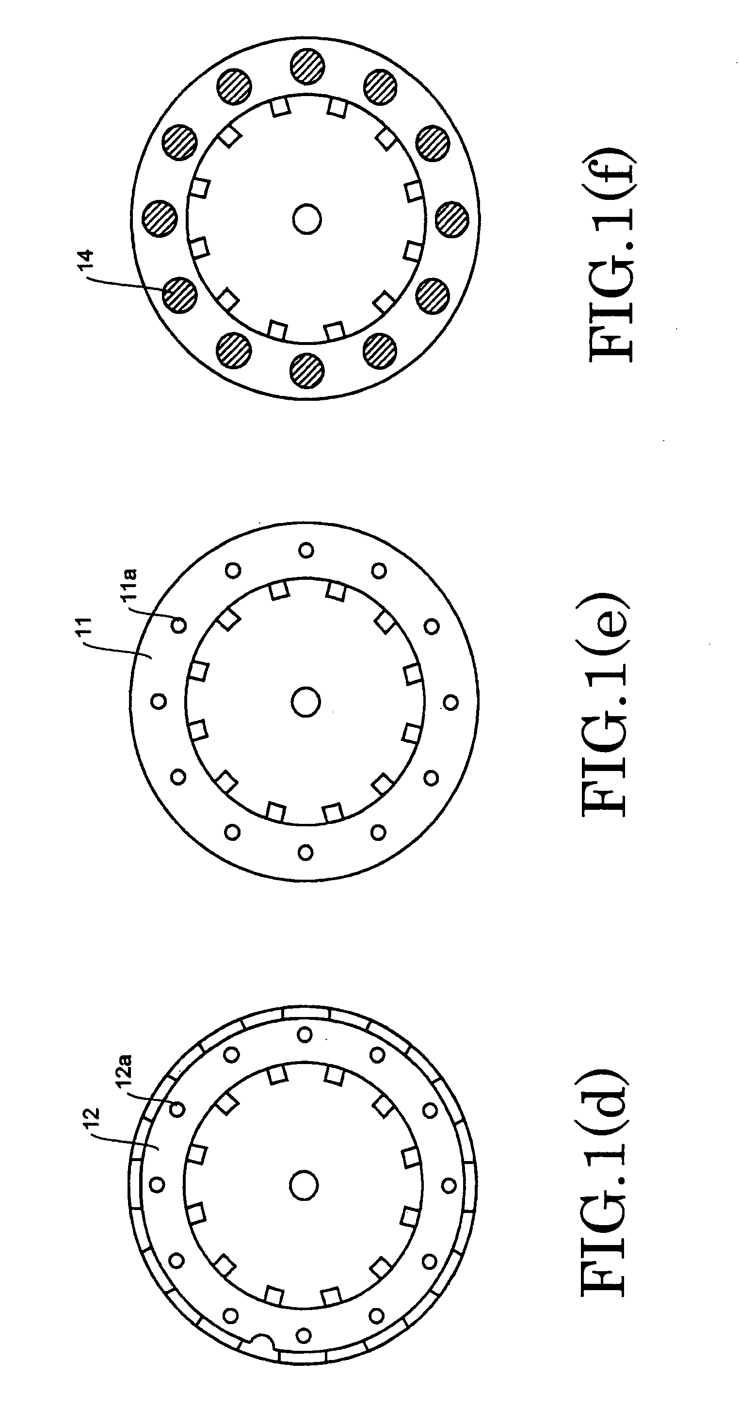
[0050] A procedure for assembling a blank member that is a workpiece machined by electric discharging is described by referring to FIGS. 1(a) through 1(f). Step 1 is shown in FIG. 1(a). A ring 11 is made of a nonmagnetic material, such as a copper alloy. The ring 11 is provided with holes 11a for injecting a curing agent 14 (described later). In the following description, the curing agent is an epoxy resin curing agent. Step 2 is shown in FIG. 1(b). A filmy insulating material (hereinafter referred to as the insulator) 12 is placed on the ring 11. The insulator 12 is provided with holes 12a for injecting the curing agent. In this case, the holes 12a are aligned with the holes 11a in the ring 11.

[0051] Step 3 is shown in FIG. 1(c). A blank material 13 from which polar elements will be fabricated is made of a soft magnetic material. The blank material 13 is provided with holes 13a for injecting the epoxy resin curing agent. The blank material 13 is placed on the insulato...

Example

Embodiment 2

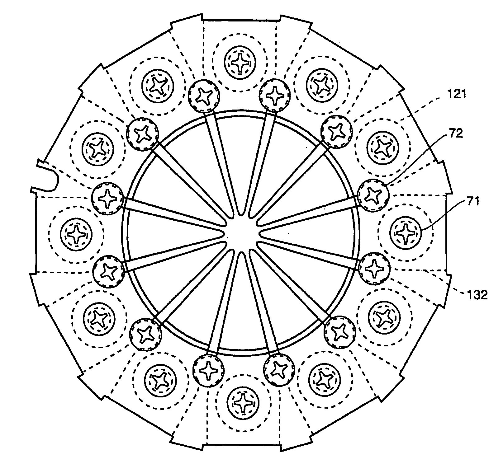
[0062] A blank member is fabricated by steps 1-6 already described in connection with FIGS. 1(a) through 1(l) in the same way as in Embodiment 1. A procedure of machining the blank member is described by referring to the plan views of FIG. 1(j) and FIG. 1(k). FIG. 1(j) and FIG. 1(k) illustrate steps 7 and 8, respectively. The blank member integrated by step 6 is set on a wire electric discharge machine (not shown) and the outer contour is machined. Because of this machining step, the discontinuous shapes of arcs 111a providing an assembly reference, slot 61, and terminal ends of the polar elements are machined.

[0063] In step 8, the multipolar element is divided by wire electric discharging subsequently to step 7, and the shapes of front ends of polar elements are formed. The portion of the multipolar element which is placed in a vacuum is completed. FIG. 1(l) is a horizontal cross section of the portion of the multipolar element which is placed in a vacuum, and shows t...

Example

Embodiment 3

[0071] Two or more slots are formed by a machining step. The number of the slots is less than the number of the polar elements. Thus, any one of the slots which gives a high positional accuracy with the azimuthal orientation of the polar elements can be selected during assembly, and the accuracy of the azimuthal angle of the polar elements can be improved.


PUM


Abstract

There is disclosed a multipole lens that can be machined with improved accuracy. A method of fabricating this lens is also disclosed. The multipole lens has a blank material from which polar elements will be fabricated. The blank material is sandwiched vertically between two layers of filmy insulator. The blank material and the two layers of filmy insulator are sandwiched vertically between an upper ring and a lower ring. These members are provided with injection holes for injecting a curing agent. The injection holes of these members are aligned. The curing agent is injected into the holes and cured. Then, the blank material is machined by electric discharge machining to form the polar elements.

Description

BACKGROUND OF THE INVENTION [0001] 1. Field of the Invention [0002] The present invention relates to a multipole lens and also to a method of fabricating it. [0003] 2. Description of Related Art [0004] In imaging apparatus, such as a scanning electron microscope, when a specimen is irradiated with an electron beam that is a charged-particle beam, aberration in the beam is corrected in order to image the specimen appropriately. In such an imaging apparatus, a multipole lens is mounted as an aberration corrector for correcting aberration in the electron beam. [0005] A known structure of this multipole lens is described, for example, in JP2-230647, where plural (e.g., 8 or 12) polar elements are mounted. The polar elements are supported by an annular holding member and by a yoke disposed outside the holding member. [0006] The multipole lens described in JP2-230647 has plural polar elements, a beam tube, and an annular yoke disposed outside the beam tube. Each of the polar elements cons...

Claims


Application Information

Patent Timeline
IPC IPC(8): H01J1/50
CPCH01J37/153H01J2237/1405H01J2237/28H01J2237/26H01J2237/1532
Inventor KAWAI, EIJI
Owner JEOL LTD
Why Eureka
Try Eureka