
High Linearity Modulation System and Modulation Method

a modulation system and linearity technology, applied in the field of modulation systems, can solve the problems of high power loss of analog amplifiers, increase in temperature of analog amplifiers, and large heat generation in analog amplifiers, and achieve high linearity

Inactive Publication Date: 2007-12-06
SAMSUNG ELECTRONICS CO LTD
View PDF1 Cites 23 Cited by
  • Summary
  • Abstract
  • Description
  • Claims
  • Application Information

AI Technical Summary

Benefits of technology

[0015]Embodiments of the present invention provide a modulation system and method having high linearity.

Problems solved by technology

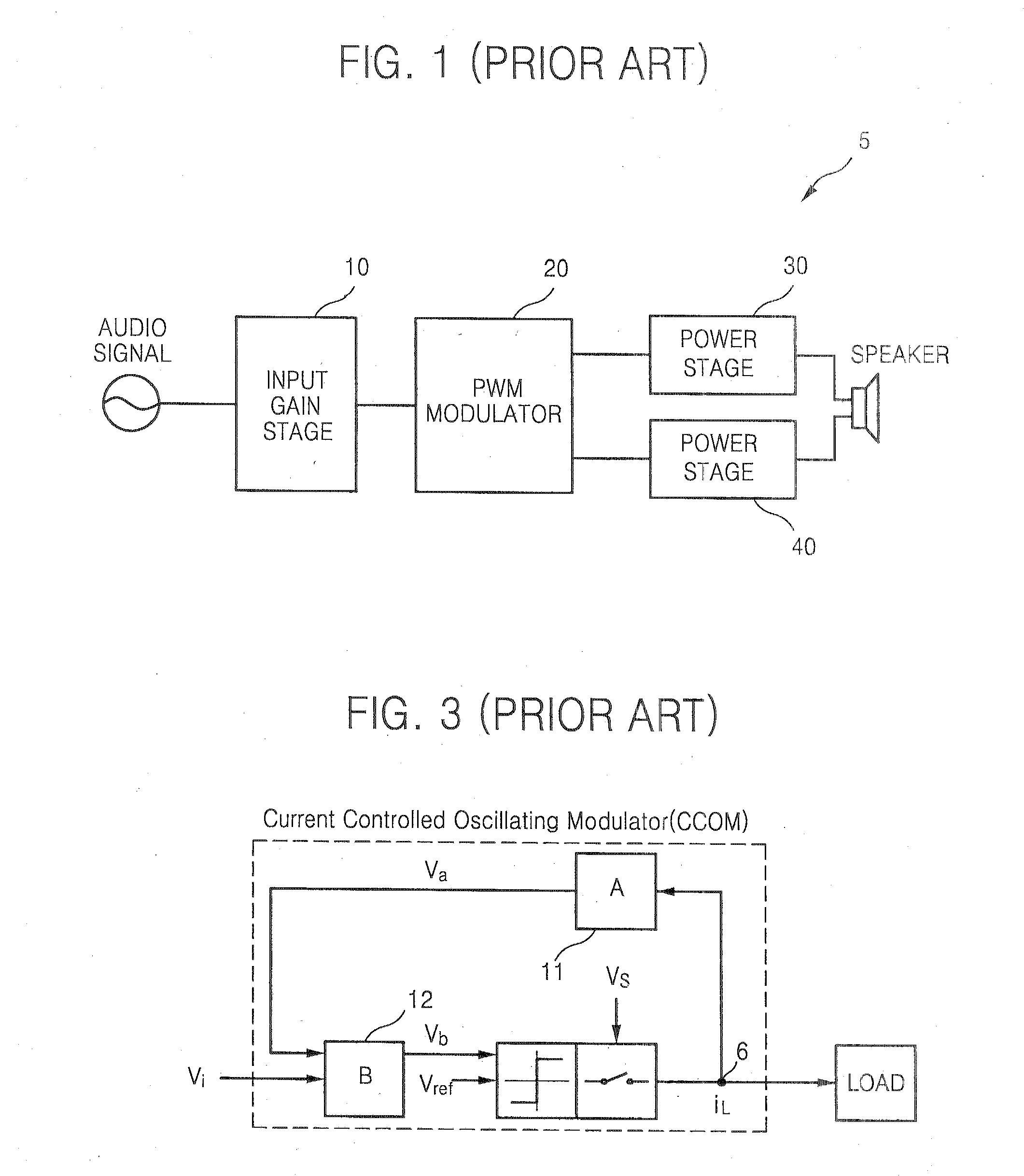
Since the analog amplifiers, for example, class A amplifiers, class B amplifiers, and class AB amplifiers, are less efficient than digital amplifiers, for example, class D amplifiers, power loss of analog amplifiers is very high.
Thus, a lot of heat is generated in analog amplifiers and the temperature of the analog amplifiers increases when in use.
Also, when the temperature of an audio apparatus including the analog amplifier increases, the analog amplifier may be damaged.
Furthermore, in an analog amplifier using a vacuum tube or a transistor, distortion of a signal may be unavoidable as a result of thermal noise due to thermal motion of electrons and the unstable linearity of an amplification device, for example, a vacuum tube or a transistor.

Method used


Image

  • High Linearity Modulation System and Modulation Method
  • High Linearity Modulation System and Modulation Method
  • High Linearity Modulation System and Modulation Method

Examples


Embodiment Construction

[0035]The attached drawings are referred to in order to gain a sufficient understanding of exemplary embodiments of the present invention.

[0036]Exemplary embodiments of the present invention are described in detail herein with reference to the attached drawings. Like reference numerals in the drawings denote like elements.

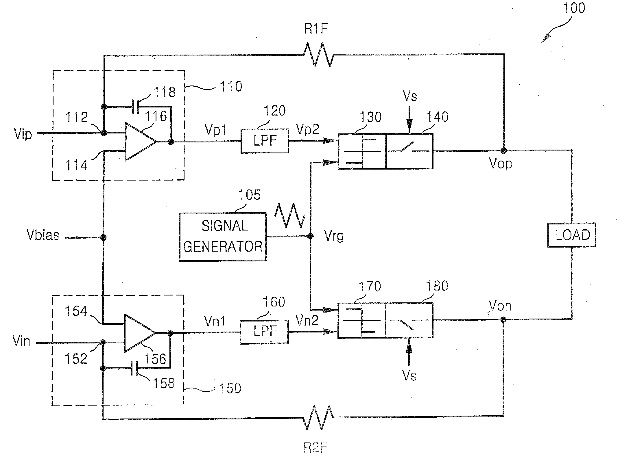
[0037]FIG. 4 is a functional block diagram of a modulation system according to exemplary embodiments of the present invention. FIG. 5 is a functional block diagram of a modulation system according to an exemplary embodiment of the present invention.

[0038]Referring to FIGS. 4 and 5, modulation systems 100 (100′ in FIG. 5) capable of reducing electromagnetic interference (EMI) include a signal generator 105, a first integrate 110 (110′ in FIG. 5), a first low pass filter (LPF) 120, a first comparator 130, a first output circuit 140, a second integrator 150 (150′ in FIG. 5), a second LPF 160, a second comparator 170, and a second output circuit 180. The first integrat...


PUM


Abstract

A modulation system and method having a high linearity. The system is a PWM modulator or a class D amplifier and includes an integrator, a low pass filter (LPF), a comparator, and an output circuit. The LPF is located before the comparator. Jitter noise produced by the comparator and / or switching noise of the output circuit are removed by feedback to the input. Thus, the linearity of the modulation system is provided.

Description

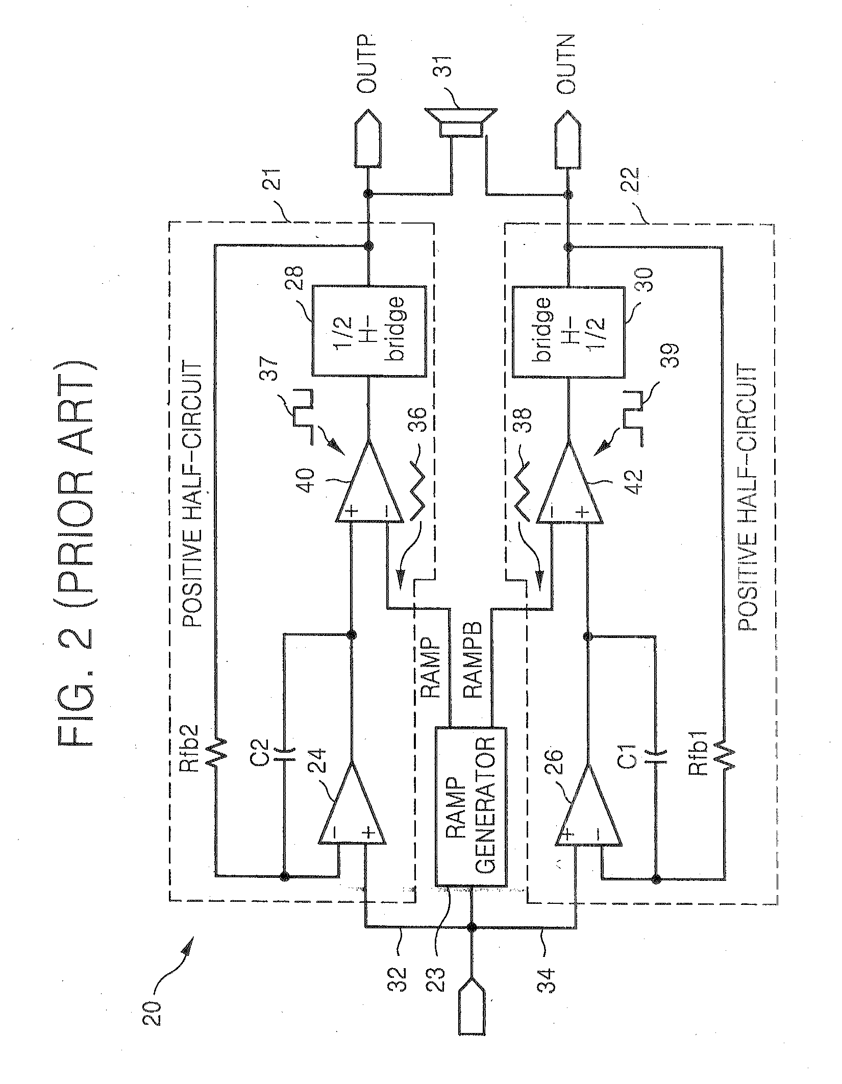
CROSS-REFERENCE TO RELATED PATENT APPLICATIONS[0001]This application claims priority under 35 U.S.C. § 119 to Korean Patent Application No. 10-2006-0050038, filed on Jun. 2, 2006, the disclosure of which is hereby incorporated by reference in its entirety.BACKGROUND OF THE INVENTION[0002]1. Technical Field[0003]The present disclosure relates to a modulation system, and more particularly, to a modulation system and method having high linearity.[0004]2. Discussion of the Related Art[0005]Typically, amplifiers are classified into analog amplifiers and digital amplifiers. The analog amplifiers include class A amplifiers, class B amplifiers, and class AB amplifiers. The digital amplifiers include class D amplifiers. Since the analog amplifiers, for example, class A amplifiers, class B amplifiers, and class AB amplifiers, are less efficient than digital amplifiers, for example, class D amplifiers, power loss of analog amplifiers is very high. Thus, a lot of heat is generated in analog amp...

Claims


Application Information

Patent Timeline
IPC IPC(8): H03F3/38
CPCH03F3/2173H03F2200/372H03F2200/351H03F2200/03H03K7/08H03F3/217
Inventor LEE, JONG-HAENG
Owner SAMSUNG ELECTRONICS CO LTD
Learn More