Automatic focusing apparatus

a focusing apparatus and automatic technology, applied in the direction of camera focusing arrangement, printers, instruments, etc., can solve the problems of low impact resistance, large power required to drive the lens driving motor, complex focusing system, etc., and achieve the effect of reducing the time required for focusing

Inactive Publication Date: 2007-12-06
CITIZEN WATCH CO LTD
View PDF3 Cites 75 Cited by
  • Summary
  • Abstract
  • Description
  • Claims
  • Application Information

AI Technical Summary

Benefits of technology

[0033] According to the present invention, the liquid crystal lens is used for adjusting the focal length, the plurality of focus signals corresponding to various focusing states are extracted in a collective manner during the transient response of the liquid crystal lens, and the maximum value of the focus sig...

Problems solved by technology

However, this method requires the use of a lens driving mechanism, and therefore has the drawbacks that the focusing system becomes complex, and that relatively large power is required to drive the lens driving motor.
This type of focusing system has the further drawback that impact resistance is generally low.
To date, however, no reports have been published on the use of the hill climbing control method in achieving focusing by varying the refractive index of a liquid crystal lens.
One possible reason for this is that, in the case of a liquid crystal lens, it takes considerable time to detect a focused position by the mounting climbing control.
However, since there is generally a finite delay before the liquid crystal can respond to a change in applied drive voltage, the process for acquiring the out-of-focus condition information has to wait until the respo...

Method used


Image

  • Automatic focusing apparatus
  • Automatic focusing apparatus
  • Automatic focusing apparatus

Examples


embodiment 1

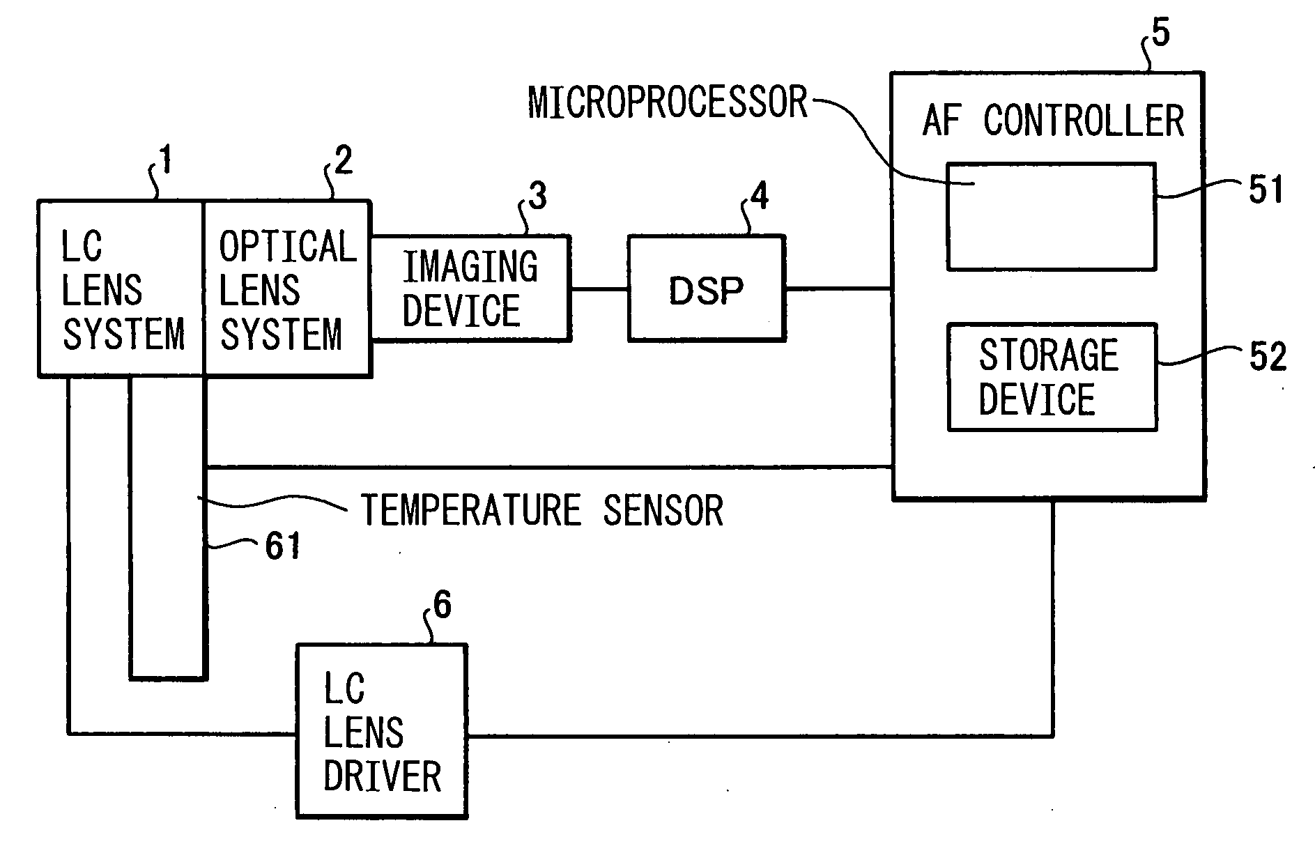
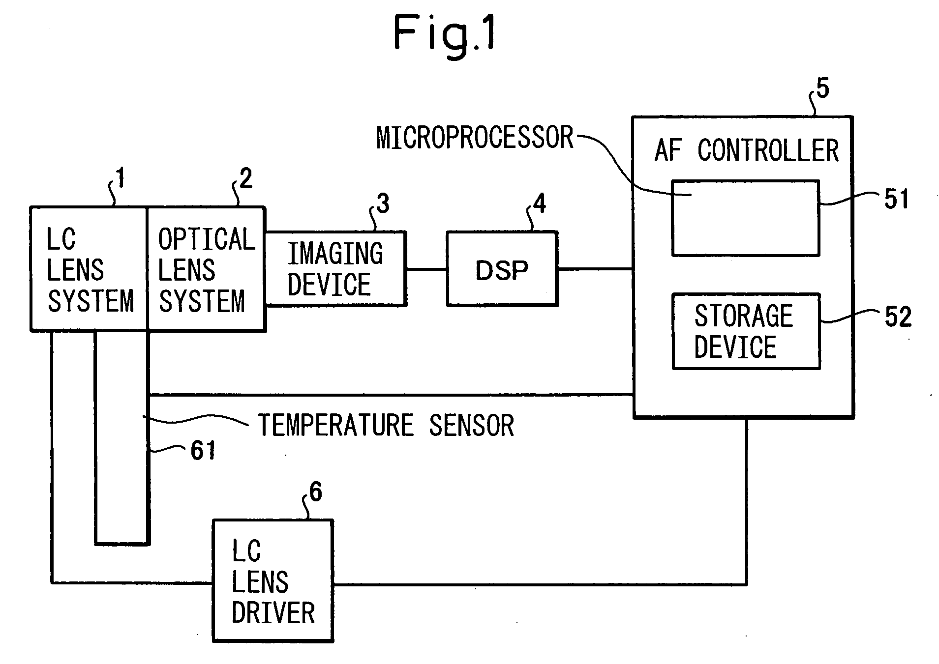
[0079]FIG. 1 is a block diagram showing the basic configuration of an automatic focusing apparatus. As shown in FIG. 1, the automatic focusing apparatus comprises a liquid crystal (LC) lens system 1, an optical lens system 2, an imaging device 3, a DSP (digital signal processor) 4, an autofocus (AF) controller 5, a liquid crystal lens driver 6, and a temperature sensor 61. The liquid crystal lens system 1 is constructed by combining a liquid crystal lens for P waves with a liquid crystal lens for S waves. The optical lens system 2 comprises a diaphragm, a group of lenses, and an infrared cutoff filter, through which an image of an object located at a prescribed distance from the optical lens system 2 is focused onto the imaging device 3. The imaging device 3 comprises an image sensor constructed from a solid-state imaging device, such as a CCD or CMOS imager, and an analog-digital converter. The temperature sensor 61 is mounted near the liquid crystal lens system 1, and is used to e...

embodiment 2

[0167]FIG. 19 is a block diagram showing the basic configuration of an automatic focusing apparatus according to the present invention. As shown in FIG. 19, the automatic focusing apparatus according to the present invention comprises a camera lens unit 70 and an autofocus controller 5. The camera lens unit 70 comprises a liquid crystal lens system 1, an optical lens system 2, an imaging device 3, a liquid crystal (LC) lens controller 100, and a temperature sensor 61. The liquid crystal lens system 1 is constructed by combining a liquid crystal lens for P waves with a liquid crystal lens for S waves. The optical lens system 2 comprises a diaphragm, a group of lenses, and an infrared cutoff filter, through which an image of an object located at a prescribed distance from the optical lens system 2 is focused onto the imaging device 3. The imaging device 3 comprises an image sensor constructed from a solid-state imaging device, such as a CCD or CMOS imager, and an analog-digital conver...


PUM


Abstract

An object of the present invention is to provide an automatic focusing apparatus which can reduce the time required to detect focused position in accordance with the operating environment by adjusting the voltage applied to a liquid crystal lens. The apparatus includes a liquid crystal lens whose focal length varies with an applied voltage, a liquid crystal lens driving unit which applies a prescribed voltage to the lens, an optical-to-electrical converter which produces an image signal from an optical image passed through the lens, a temperature sensor which detects temperature near the lens, and a control unit which extracts a plurality of focus signals by adjusting the prescribed voltage and controlling the driving unit based on the temperature or on the image signal acquisition period of the converter, and which controls the driving unit based on the extracted plurality of focus signals so that a maximum focus signal is achieved.

Description

[0001] The Applicant claims the right to priority based on Japanese Patent Application JP 2006-151394, filed on May 31, 2006, and the entire content of JP 2006-151394 is hereby incorporated by reference. FIELD OF THE INVENTION [0002] The present invention relates to an automatic focusing apparatus, and more particularly to an automatic focusing apparatus that uses a liquid crystal lens for adjusting focal length, wherein the automatic focusing apparatus extracts a plurality of focus signals corresponding to various focusing states from an image signal obtained from an optical image focused through the liquid crystal lens during the transient response of the liquid crystal lens, and detects focused position by detecting the peak value of these focus signals. BACKGROUND OF THE INVENTION [0003] Traditionally, a method that achieves focusing by moving a lens or lenses has been widely employed to implement a focusing system for varying the focal length or focus position of an optical sys...

Claims


Application Information

Patent Timeline
IPC IPC(8): G09G3/36
CPCG02B7/38G02F1/13306G02F1/29H04N5/23212G02F2203/60G03B3/00G02F2001/294G02F1/294H04N23/673
Inventor KAGEYAMA, YASUHIRO
Owner CITIZEN WATCH CO LTD
Why Eureka
Try Eureka