Liquid crystal display device, driving method of the same, and electronic device using the same

a technology of liquid crystal display and driving method, which is applied in the direction of static indicating devices, non-linear optics, instruments, etc., can solve the problems of inability to express correct gray scale and difficult control of backlight, and achieve the effect of low response speed of liquid crystal elements

Active Publication Date: 2007-12-06
SEMICON ENERGY LAB CO LTD
View PDF44 Cites 120 Cited by
  • Summary
  • Abstract
  • Description
  • Claims
  • Application Information

AI Technical Summary

Benefits of technology

[0042]In accordance with the present invention, when the transmissivity of a liquid crystal element is changed over time in a plurality of lighting periods which are obtained by dividing one frame period, a display device can express a correct gray scale even though the response speed of the liquid crystal element is low. In addition, in each lighting period, a backlight unit supplies light of various colors, whereby full-color display can be performed in one pixel.

Problems solved by technology

This is because a correct gray scale cannot be expressed in some cases depending on the writing timing of a video signal and the switching timing of R, G, and B of a backlight.
Therefore, since a display device generally includes a number of pixels, control of a backlight becomes quite difficult.

Method used


Image

  • Liquid crystal display device, driving method of the same, and electronic device using the same
  • Liquid crystal display device, driving method of the same, and electronic device using the same
  • Liquid crystal display device, driving method of the same, and electronic device using the same

Examples


embodiment mode 1

(Configuration of a Display Device Used in the Present Invention)

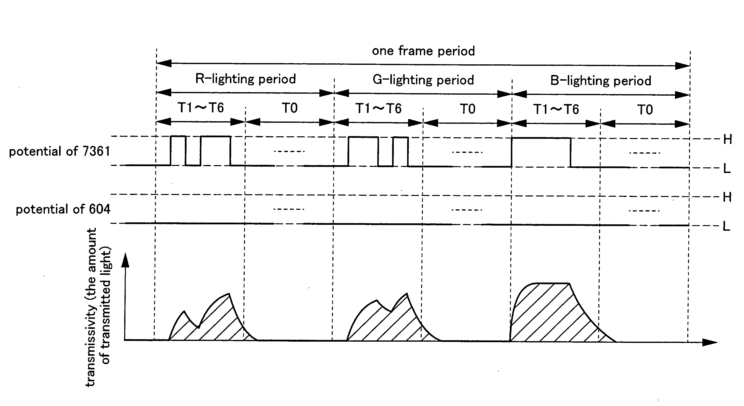
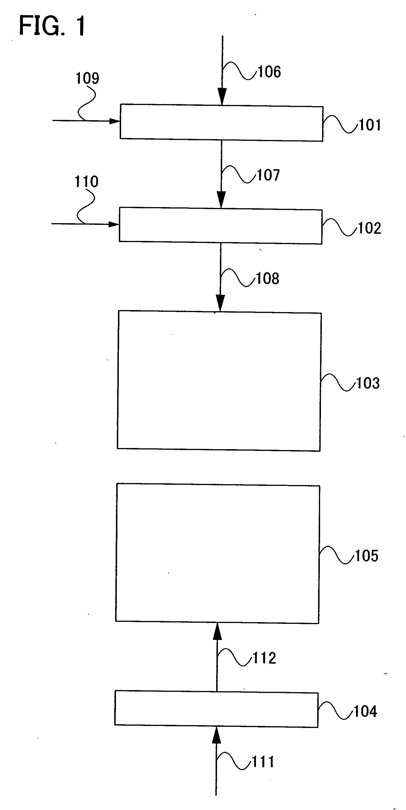
[0113]First, an overview of a configuration of a display device used in the present invention will be explained with reference to FIG. 1.

[0114]FIG. 1 shows a configuration example of a system block diagram of a display device used in the present invention. The display device used in the present invention includes a converter 101, a driving portion 102, a display portion 103, a backlight controller 104, and a backlight unit 105.

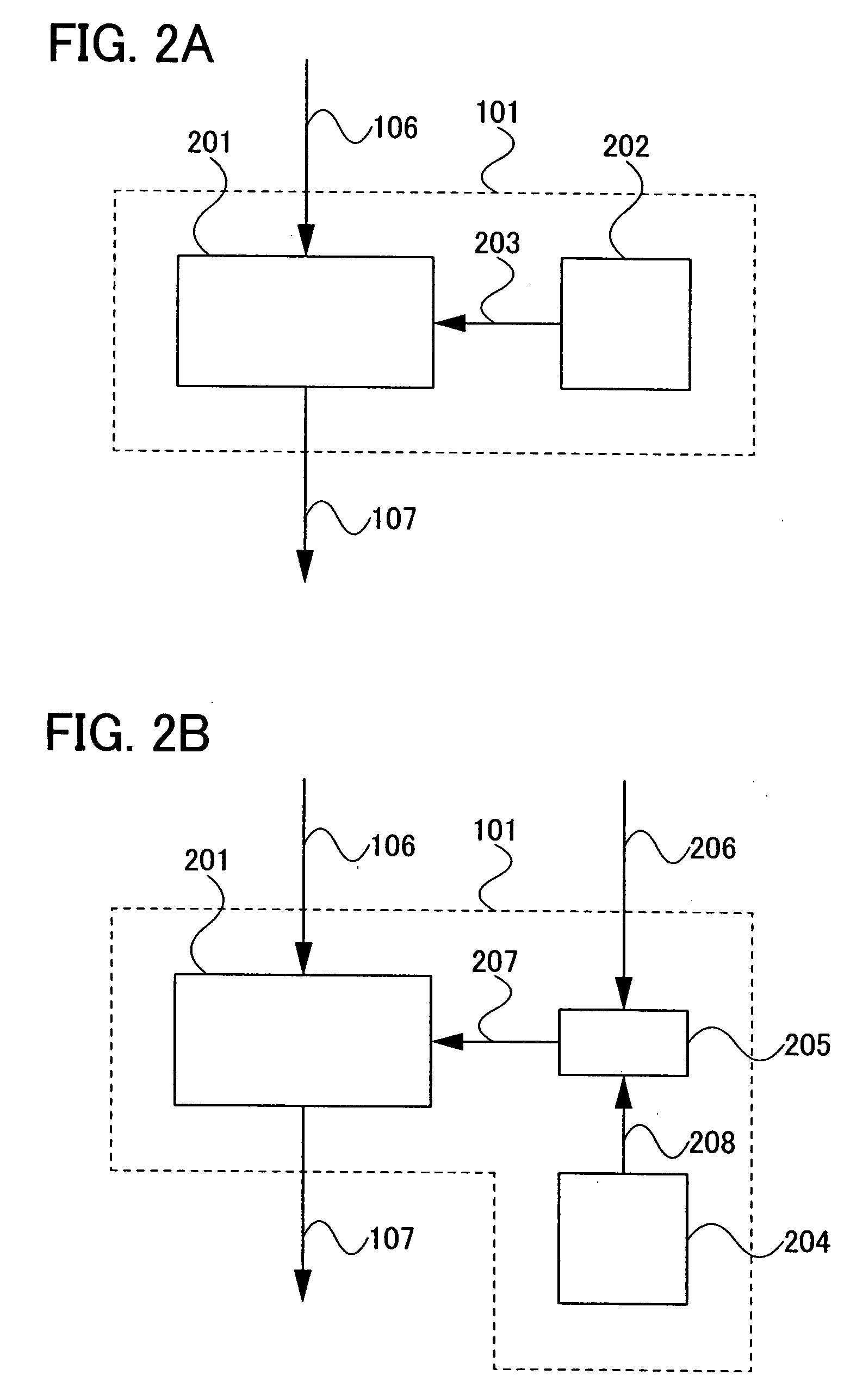
[0115]In FIG. 1, a gray scale signal 106 and a control signal 109 are input to the converter 101. The converter 101 outputs a driving portion control signal 107 to the driving portion 102. It is to be noted that the gray scale signal 106 is image data (such as a moving image or a still image) which is to be displayed on the display portion 103, and the control signal 109 is a signal which serves as a reference such as a clock pulse for driving the converter 101. The driving portion control signal...

embodiment mode 2

[0318]In this embodiment mode, a pixel structure in a case where the display device used in the present invention is used as a semi-transmissive display device will be explained with reference to FIGS. 24A and 24B.

[0319]In FIG. 24A, one pixel 2403 is divided into a reflective region 2401 and a transmissive region 2402. The reflective region 2401 is provided with a color filter, whereas the transmissive region 2402 is not provided with a color filter.

[0320]FIG. 24B is a cross-sectional view taken along a line A-B of the pixel 2403 in FIG. 24A. A glass substrate 2411, a transistor layer 2412, an insulating layer 2413, a reflective electrode layer 2414, a transparent electrode layer 2415, a liquid crystal layer 2416, an insulating layer 2417, a color filter 2418, and a glass substrate 2419 are provided.

[0321]As compared to the transmissive region 2402, in the reflective region 2401, the transistor layer 2412, the reflective electrode layer 2414, the insulating layer 2417, and the color...

embodiment mode 3

[0326]In this embodiment mode, various liquid crystal modes which can be applied to the display device used in the present invention will be explained.

[0327]Various liquid crystal modes which can be applied to a liquid crystal display device of this embodiment mode will be explained.

[0328]FIGS. 26A1 and 26A2 each show a schematic view of a liquid crystal display device of a TN mode.

[0329]A layer 2600 including a display element is interposed between a first substrate 2601 and a second substrate 2602, which are provided so as to face each other. A first polarizer-including layer 2603 is stacked on the first substrate 2601 side, and a second polarizer-including layer 2604 is stacked on the second substrate 2602 side. The first polarizer-including layer 2603 and the second polarizer-including layer 2604 are arranged so as to be in a cross nicol state.

[0330]Although not shown in the drawing, a backlight and the like are provided on the outer side of the second polarizer-including layer....


PUM


Abstract

It is an object to provide a display module which can display a correct gray scale by a field sequential driving method and an electronic device including the display module. One frame period is divided into a plurality of lighting periods, and in each of the plurality of lighting periods, signals are supplied to a pixel a plurality of times, whereby the transmissivity of a liquid crystal element is changed over time. Accordingly, even with the use of a liquid crystal element with low response speed as a display element, a correct gray scale can be expressed. In addition, the transmissivity of the liquid crystal element is set at 0% or a backlight is controlled not to emit light in switching of lighting of a backlight or switching of lighting periods, whereby a more correct gray scale can be expressed.

Description

BACKGROUND OF THE INVENTION[0001]1. Field of the Invention[0002]The present invention relates to a liquid crystal display device, in particular, a driving method of a liquid crystal display device. In addition, the present invention relates to a liquid crystal display device using the driving method and an electronic device including the liquid crystal display device.[0003]2. Description of the Related Art[0004]In recent years, display devices such as a liquid crystal display device and a light-emitting display device have been actively developed to be used for a personal computer, a mobile device, and a liquid crystal television. In particular, the display devices are required to have a high resolution. However, in the current display devices, a pixel portion is formed using three pixels for red (hereinafter abbreviated as R), green (hereinafter abbreviated as G), and blue (hereinafter abbreviated as B); thus, there is a limitation on increase in resolution of the liquid crystal di...

Claims


Application Information

Patent Timeline
Patent Type & Authority Applications(United States)
IPC IPC(8): G09G3/36
CPCG02F1/133514G02F1/133555G02F1/133603G09G3/3413G09G3/3426G09G3/3648G09G2320/0252G09G3/3688G09G2300/0452G09G2300/0456G09G2300/0491G09G2300/0809G09G3/3677
Inventor KIMURA, HAJIMEUMEZAKI, ATSUSHIYAMAZAKI, SHUNPEI
Owner SEMICON ENERGY LAB CO LTD
Why Eureka
Try Eureka