Access to printing material container

a printing material and container technology, applied in the field of storage devices, can solve the problems of not being able to conclude normal writing operations of data, not being able to recycle techniques, and practicably impossible to rewrite the identification information stored in each storage device, etc., and achieve the effect of rewriting

Inactive Publication Date: 2007-12-06
SEIKO EPSON CORP
View PDF18 Cites 5 Cited by
  • Summary
  • Abstract
  • Description
  • Claims
  • Application Information

AI Technical Summary

Benefits of technology

[0009] The object of the present invention is thus to provide a storage device that enables identification data to be readily rewritten and ensures normal completion of a data writing operation in a short time period.

Problems solved by technology

The former technique storing the physical identification information in the storage device, for example, with a pull-up resistance, however, it is practically impossible to rewrite the identification information stored in each storage device.
This technique is accordingly not suitable for recycle.
In the case of accidental cutoff of the power supply during the access to the storage device, the writing operation of data can not be concluded normally.
This undesirably requires the heavy wiring load of the signal lines and complicates the layout design.
Only one chip select signal line is utilized for access, which worsens the utilization efficiency of the signal lines.

Method used

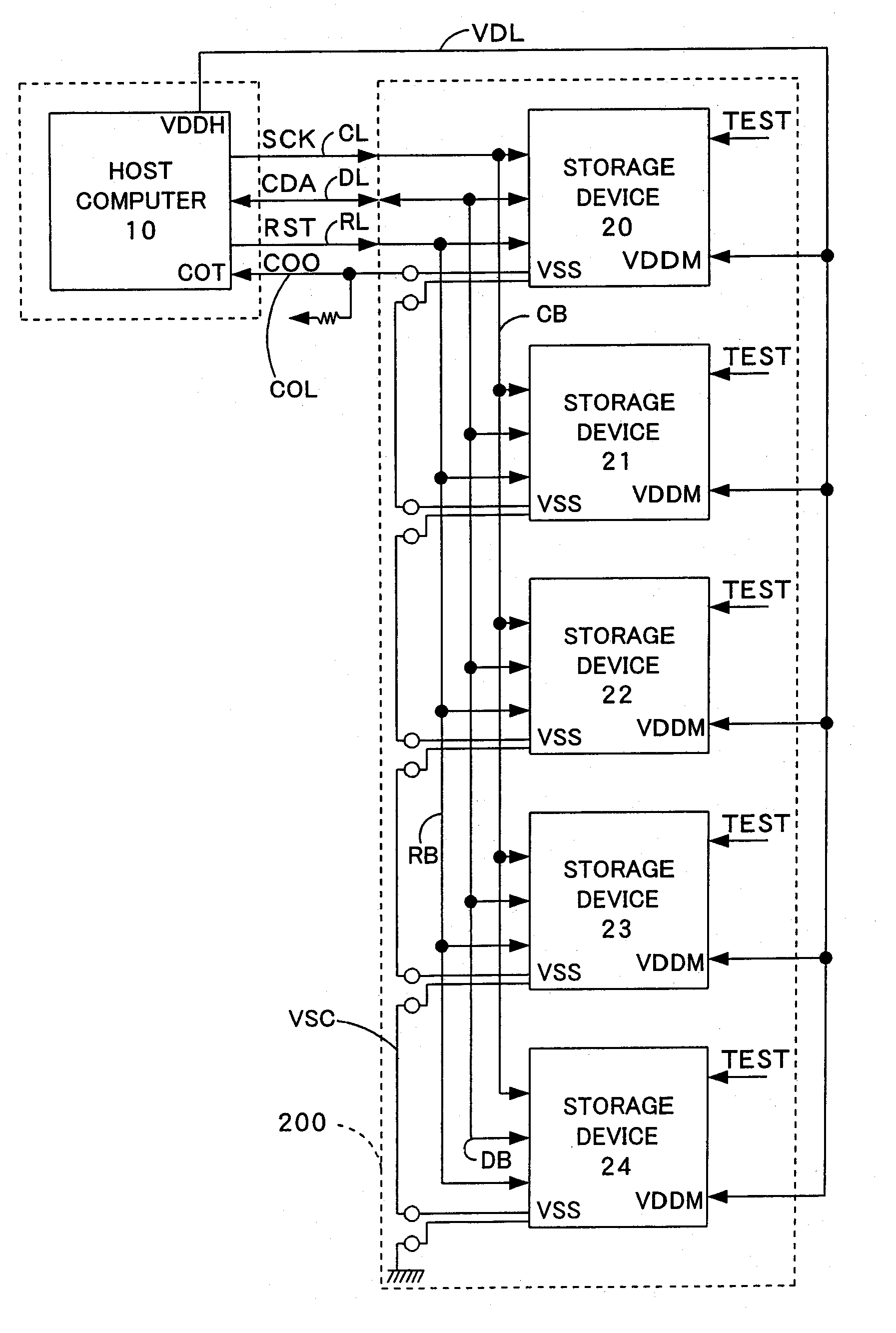
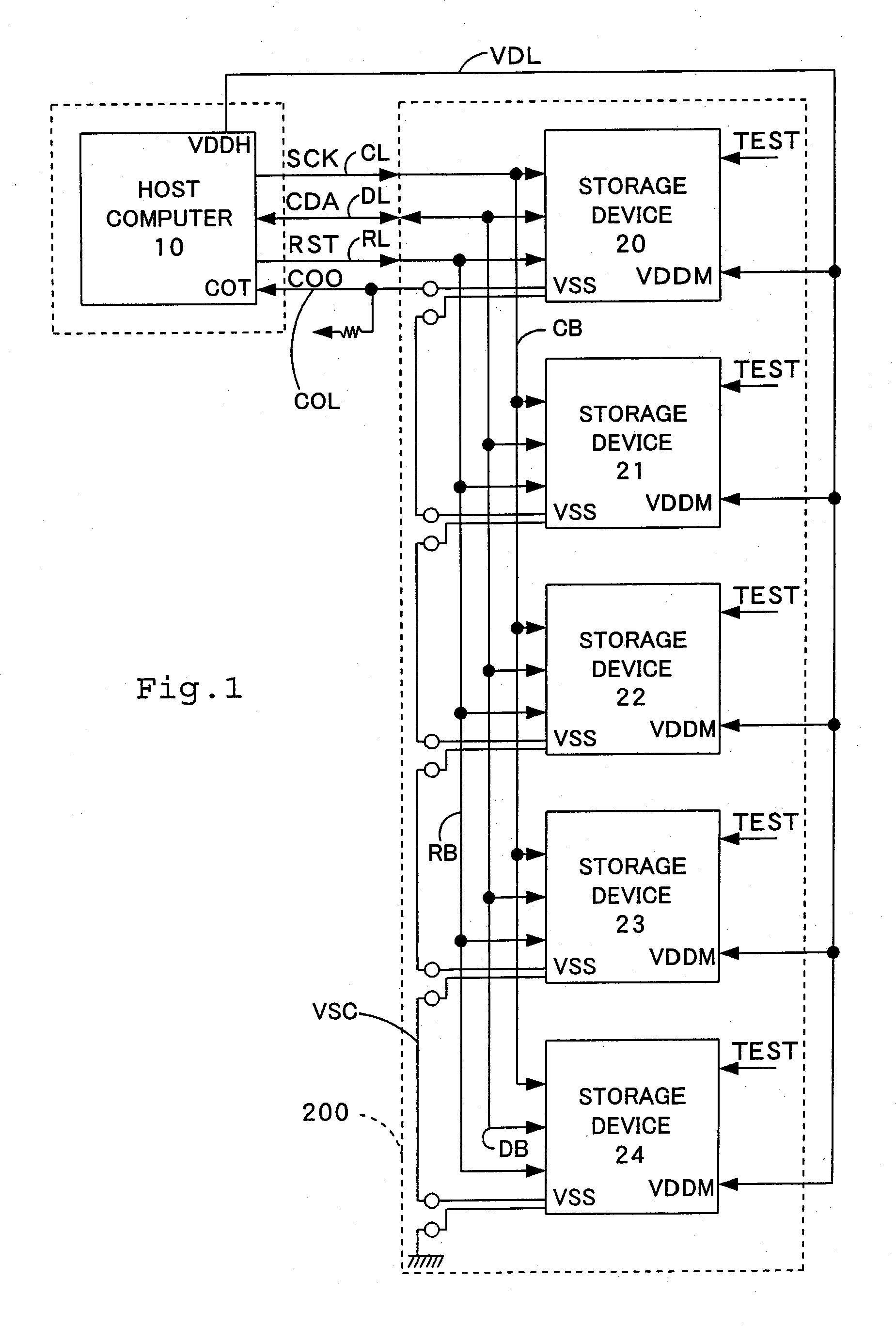
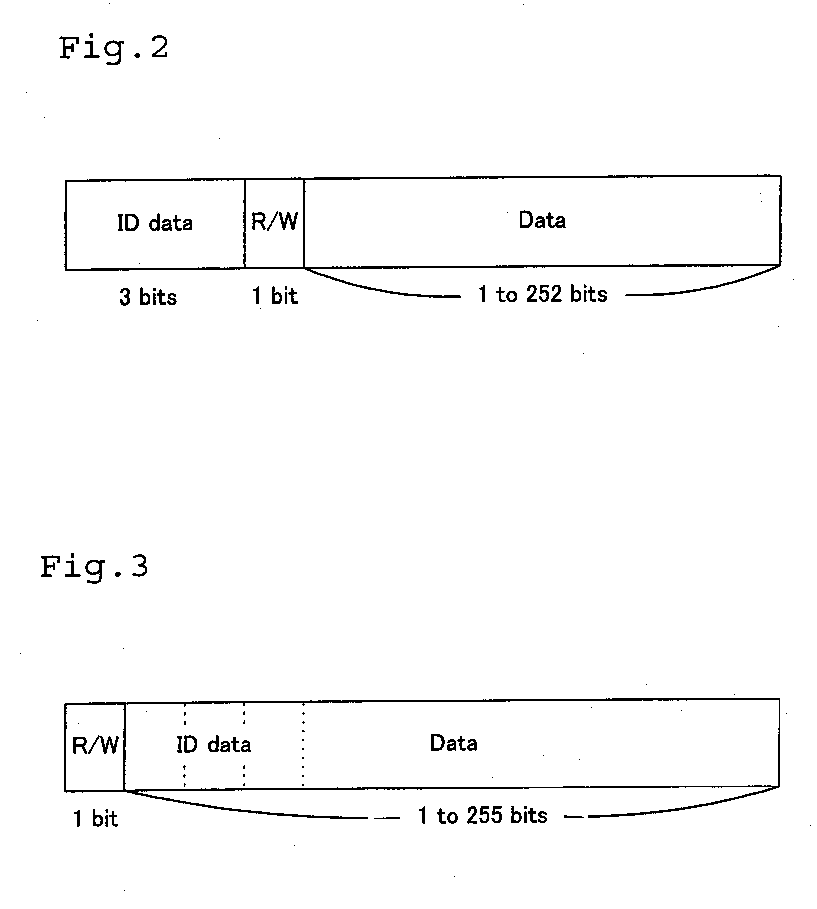

Image

  • Access to printing material container
  • Access to printing material container
  • Access to printing material container

Examples


third embodiment

D. Process of Writing Identification Data into Storage Device in Test Mode (in factory Setting Process) in Third Embodiment

[0139] The following describes a process of writing identification data and initial data into the storage devices 20, 21, 22, 23, and 24 in the test mode in a third embodiment of the present invention. FIG. 11 is a flowchart showing a routine of the writing process in the test mode in the third embodiment. FIG. 12 shows one example of connection between a host computer for testing and a storage device to actualize the writing process in the test mode in the third embodiment.

[0140] The writing process in the test mode according to the third embodiment is applied for the storage device having the identical internal circuit structure with that of the storage device 20 included in the storage system of the first embodiment. The respective constituents are thus expressed by the like numerals and are not specifically described here. The processing of the third embodi...

fourth embodiment

E. Process of Writing Identification Data into Storage Device in Test Mode (in factory Setting Process) in Fourth Embodiment

[0146] The following describes a writing process in the test mode in a fourth embodiment of the present invention. FIG. 13 is a flowchart showing a routine of the writing process in the test mode in the fourth embodiment. FIG. 14 shows one example of connection between a host computer for testing and a storage device to actualize the writing process in the test mode in the fourth embodiment. The writing process of the fourth embodiment is applied for the storage device having the same internal circuit structure as that of the storage device 40 of the second embodiment. The respective constituents are thus expressed by the like numerals and are not specifically described here. The process of the fourth embodiment is characterized by the structure where the storage device 40 does not have the test terminal TT or the factory setting unit 206 to invalidate the ID c...


PUM


Abstract

The present invention provides a storage device that enables identification data to be readily rewritten and ensures normal completion of a data writing operation in a short time period. In the storage device of the invention, an ID comparator determines whether or not identification data transmitted from a host computer coincides with identification data stored in a memory array. In the case of coincidence, the ID comparator sends an access enable signal EN to an operation code decoder. The operation code decoder analyzes a write / read command, switches over a direction of data transfer with regard to the memory array based on a result of the analysis, and requires an I / O controller to change a high impedance setting of a signal line connecting with a data terminal DT. This series of processing allows access to an address in the memory array specified by a count on an address counter.

Description

CROSS-REFERENCE TO RELATED APPLICATION [0001] This application is a continuation of copending application Ser. No. 11 / 360,479, filed on Feb. 24, 2006.BACKGROUND OF THE INVENTION [0002] 1. Field of the Invention [0003] The present invention relates to storage devices that are mutually connected via a bus. More specifically the present invention pertains to a technique of identifying a desired storage device among a plurality of storage devices that are connected with one another via a bus. [0004] 2. Description of the Related Art [0005] A variety of techniques have been proposed to select a desired storage device among a plurality of storage devices (memories) included in a memory module and carry out a writing / reading operation of data into and from the selected storage device. In a system including a plurality of storage devices connecting with a data signal line and a clock signal line via a bus, one practical technique causes identification information to be stored in advance in ...

Claims


Application Information

Patent Timeline
Patent Type & Authority Applications(United States)
IPC IPC(8): G06K15/00B41J2/175B41J13/10G06F12/14G06F13/00G06F21/62G06F21/79
CPCB41J2/17546B41J13/103G06K15/00B41J2202/17B41J29/393
Inventor ASAUCHI, NOBORU
Owner SEIKO EPSON CORP
Why Eureka
Try Eureka