
Laser apparatus for generating high energy pulses of short duration, and process for generating said laser pulse

a laser and high energy pulse technology, applied in the direction of electrical apparatus, laser details, optical resonator shape and construction, etc., can solve the problems of complex intrinsic, high cost of traditional devices, and high system reliability risks, and achieve high spatial quality

Inactive Publication Date: 2007-12-06
BRIGHT SOLUTIONS
View PDF8 Cites 5 Cited by
  • Summary
  • Abstract
  • Description
  • Claims
  • Application Information

AI Technical Summary

Benefits of technology

[0008]The technical aim of the present invention is therefore to provide a laser apparatus for generating high energy pulses of short duration and a process for generating said laser pulse by which the stated technical drawbacks of the known art are eliminated; in particular, according to the invention the laser apparatus emits pulses with relatively high energies (more than 100 μJ) of short duration (less than 1 ns) and with high spatial quality (i.e. the laser beam which propagates has a divergence limited by diffraction or, in other words, the laser beam opens as a cone during propagation to an extent close to the physically possible theoretical minimum).
[0010]Another object of the invention is to provide an apparatus which is very reliable.

Problems solved by technology

However both microchip laser apparatuses and mode locking laser apparatuses have a very complex intrinsic structure as they are provided with a low power laser source and an amplifier for the low power pulse; this requires double electronic control and regulator circuits (for the laser source and for the amplifier), with risks for system reliability.
Moreover, the traditional devices (in particular the mode locking apparatus but also the microchip apparatus) are very costly (the amplifier is an element which contributes substantially to the overall apparatus cost).

Method used


Image

  • Laser apparatus for generating high energy pulses of short duration, and process for generating said laser pulse
  • Laser apparatus for generating high energy pulses of short duration, and process for generating said laser pulse
  • Laser apparatus for generating high energy pulses of short duration, and process for generating said laser pulse

Examples


Embodiment Construction

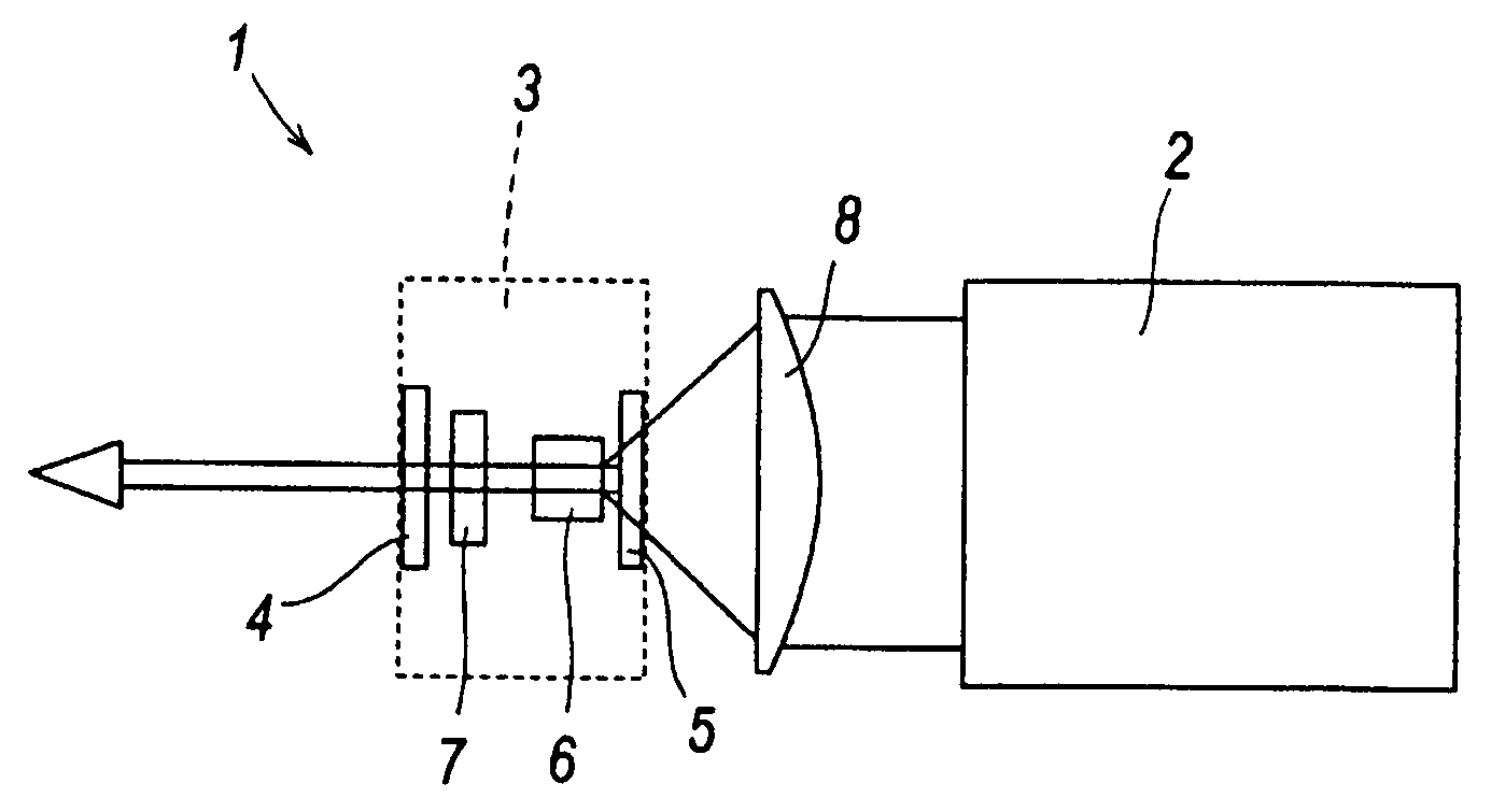
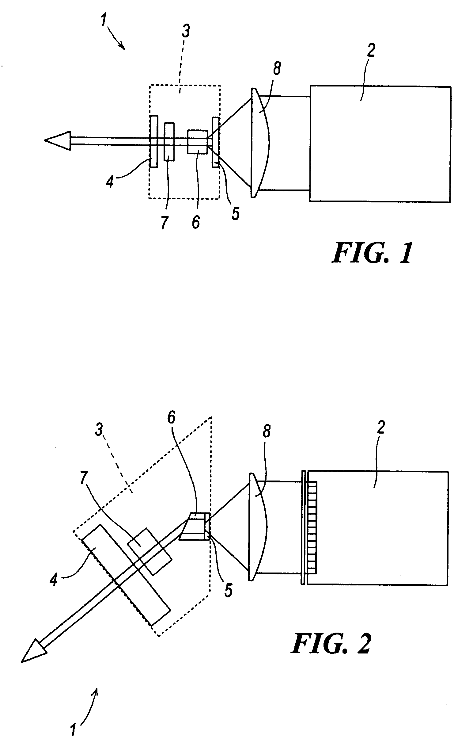
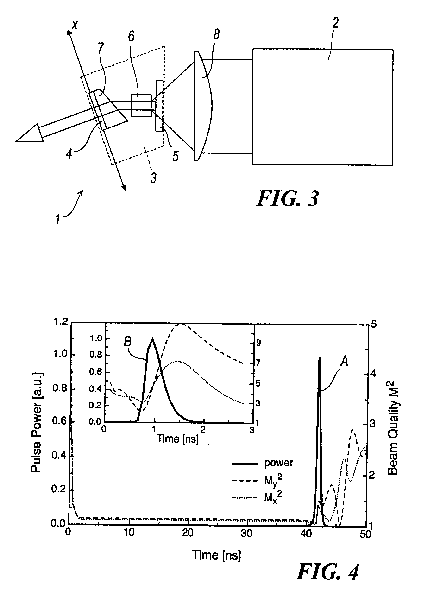
[0018]With reference to said figures, these show a laser apparatus for generating high energy pulses of short duration indicated overall by the reference numeral 1.

[0019]The laser apparatus 1 comprises a pumping laser source 2 and a miniaturized optical cavity 3, the term miniaturized meaning that it has a length of just a few centimeters (less than 15 millimeters in the preferred embodiments), defined by a pair of mirrors 4, 5, in which an active crystal 6 and an absorber 7 are housed.

[0020]A lens or optical system is provided between the laser source 2 and the mirror 5 to focus the pumping beam 8.

[0021]The laser apparatus is of the passive Q-switching type, i.e. its operation is based on solid state saturable absorbers (such as Cr:YAG), the resonant radiation absorption losses of which decrease as the radiation intensity increases; advantageously the initial absorber transmission is not greater than 0.5.

[0022]The laser source 2 typically comprises a pumping diode of power at least...


PUM


Abstract

The laser apparatus for generating high energy pulses of short duration comprises a pumping laser source and a miniaturized cavity defined by a pair of mirrors in which an active crystal and an absorber are housed. The active crystal presents a gain greater than 10 dB in double pass, said absorber being a saturable absorber. The process for generating a laser pulse consists of generating a beam of modes within a cavity and amplifying only one of the modes, so that the resultant signal presents a very limited duration but a very high intensity, with a spatial quality close to the diffraction limit.

Description

FIELD OF THE INVENTION[0001]The present invention relates to a laser apparatus for generating high energy pulses of short duration and to a process for generating said laser pulse.BACKGROUND OF THE INVENTION[0002]Laser pulses having the stated characteristics (for example with a duration of less than 1 ns and energy of some hundreds of microjoules) are used in many applications, such as micro-machining, photomask repair, and telemetry.[0003]The heat release is smaller than that which accompanies pulses with a duration of an order of magnitude longer, enabling for example more precise machining details to be obtained, with reduced probability of irregular fusion residues and fractures due to thermal stress.DISCUSSION OF THE RELATED ART[0004]Laser apparatuses with these characteristics are formed using low energy monolithic microchip laser sources for generating sub-nanosecond pulses of a few microjoules; the low energy pulses are then amplified to energy levels sufficient for the req...

Claims


Application Information

Patent Timeline
Patent Type & Authority Applications(United States)
IPC IPC(8): H01S3/091H01S3/113H01S3/08H01S3/092
CPCH01S3/0604H01S3/0615H01S3/08031H01S3/08045H01S3/09415H01S3/113H01S3/1611H01S3/1671
Inventor PICCINNO, GIULIANO
Owner BRIGHT SOLUTIONS
Learn More