Bookbinding Apparatus

a technology for bookbinding and press members, which is applied in the direction of electrographic process apparatus, instruments, printing, etc., can solve the problems of reducing achieve the effects of increasing the traveling speed of the spine-creasing press members, uniform thickness, and prolonging the holding tim

Active Publication Date: 2007-12-06
NISCA KK
View PDF6 Cites 19 Cited by
  • Summary
  • Abstract
  • Description
  • Claims
  • Application Information

AI Technical Summary

Benefits of technology

[0017]The control means controls the shift means to hold the spine-creasing press members in place at the spine-creasing position when they have folded the cover sheet over the sheet bundle. This holding time can be varied according to the basis weight (or more precisely, grammage) of the sheet bundle, the material and/or the thickness of the sheet bundle. This makes it possible for the adhesive to securely harden between the sheet bundle and cover sheet after the folding process by the spine-creasing press members to ensure a quality bond. Note that in such case, the control means controls the shift means to hold the spine-creasing press members at the spine-creasing position for the holding time preset according to the grammage or the thickness of the sheet bundle. If the grammage of the sheet bundle is high, or the sheet bundle is thick, the control means lengthens the holding time.
[0018]Also, the control means controls the shift means to slow the traveling speed of the spine-creasing press members as they approach the spine-creasing position when they are moved from their standby positions to the spine-creasing position. This makes it possible to achieve a fold at a uniform thickness without the still-softened a

Problems solved by technology

This also delays the spine-creasing press members when handling a thick

Method used


Image

  • Bookbinding Apparatus
  • Bookbinding Apparatus
  • Bookbinding Apparatus

Examples


Embodiment Construction

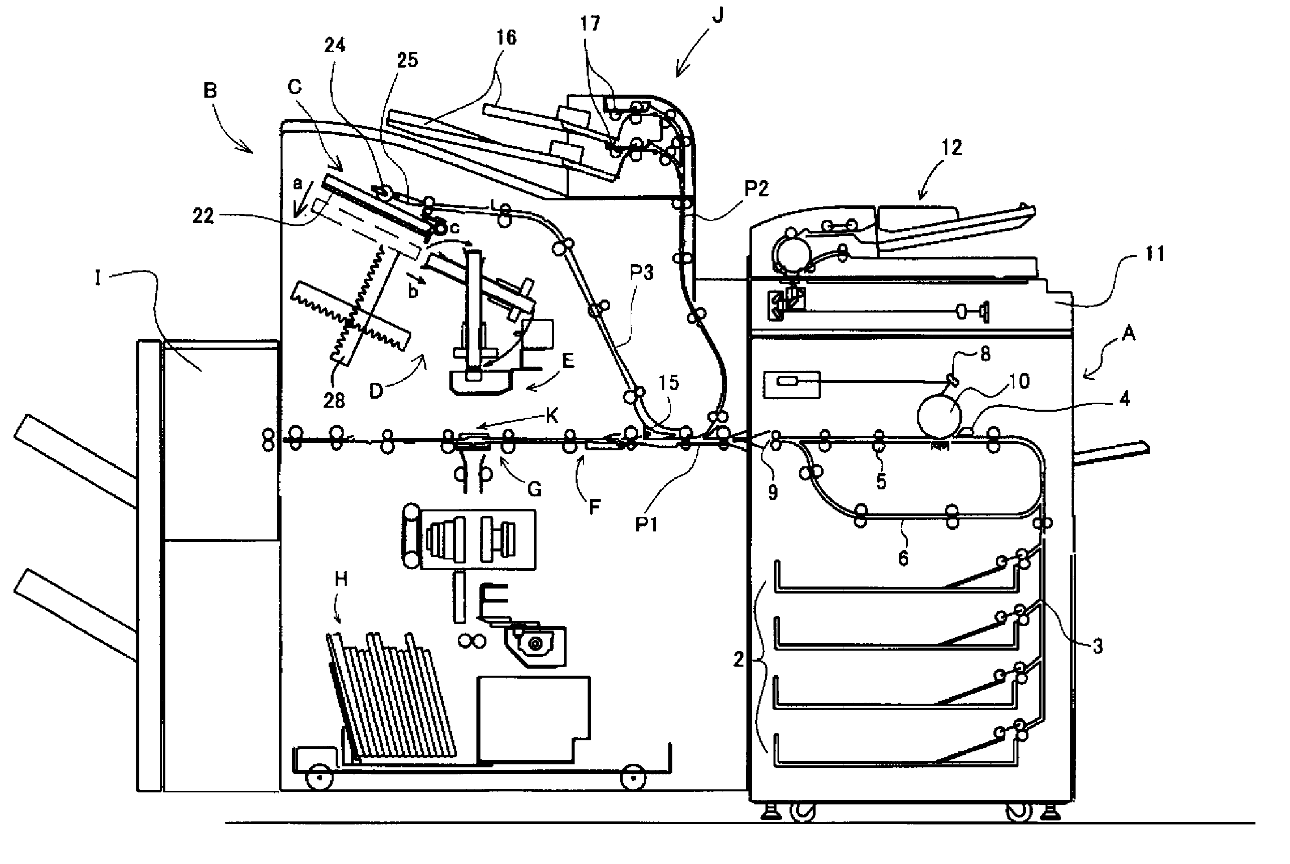
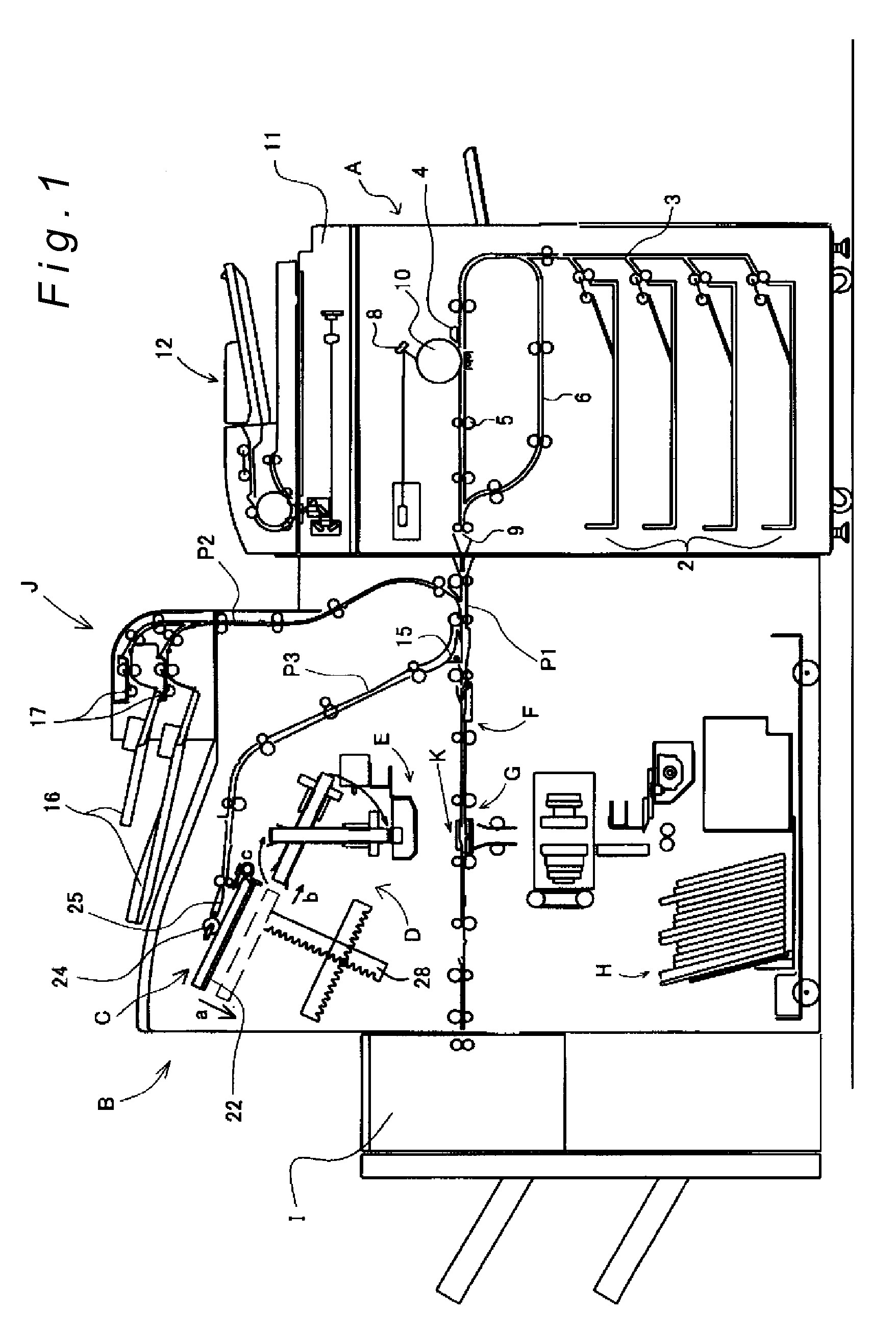
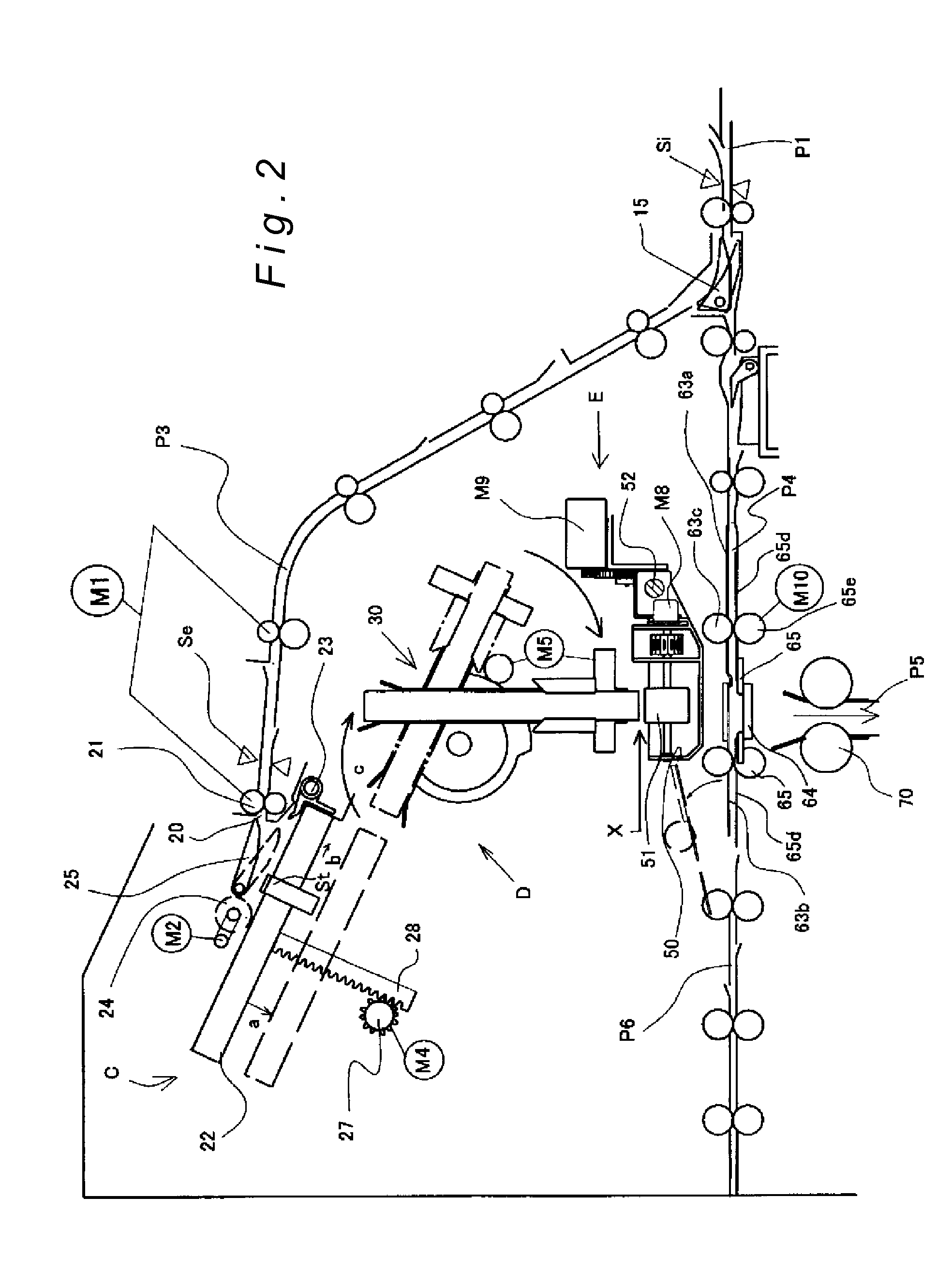
[0030]Preferred embodiments of the present invention will now be explained with reference to the drawings provided. FIG. 1 is an explanatory view of the overall configuration of the bookbinding apparatus according to the present invention; FIG. 2 is an expanded view of the essential part thereof.

[0031]The bookbinding apparatus of the present invention, as shown in FIG. 1, is connected to an image forming apparatus A. The bookbinding apparatus aligns sheets formed with images at the image forming apparatus A into a sheet bundle, then applies adhesive to the spine part of the sheet bundle. Finally, a cover sheet is joined to and pressed against the spine part of the sheet bundle thereby forming a booklet by that apparatus. The cover sheet is supplied from the image forming apparatus or an inserter device from a perpendicular direction that intersects the sheet bundle conveyance in path. FIG. 1 shows such an image forming system. The following will now explain the image forming apparat...


PUM


Abstract

In binding a cover sheet together with a sheet bundle, ever-accurate spine-creasing irrespective of bundle thickness is made possible. A sheet stacker stacks sheets into bundles, an adhesive applicator applies adhesive to a spine part of the sheet bundles, and a cover-sheet binder binds cover sheets together with the spine parts. The cover-sheet binder is constituted from a left-and-right pair of spine-creasing press members arranged free to shift between standby and spine-creasing positions; a shifter that reciprocates the spine-creasing press members between the standby and spine-creasing positions; and a controller. The controller functions to vary, in accordance with sheet bundle thickness, any of: (1) the standby position of the press members; (2) the start time of an operation whereby the press members are shifted from the standby to the spine-creasing position; or (3) the traveling speed of the press members in shifting from the standby to the spine-creasing position.

Description

BACKGROUND OF THE INVENTION[0001]1. Technical Field[0002]The present invention—involving bookbinding apparatuses that collate sheets onto which images have been formed in an image-forming or like apparatus, and that bind them into books by applying adhesive to the spine part of blocks of the sheets and binding them together with a cover sheet—relates to casing-in bookbinding apparatuses that join sheet blocks, onto the spine part of which glue has been applied, to the middle portion of a cover sheet, and spine-crease the cover sheet.[0003]2. Description of the Related Art[0004]Generally, this kind of bookbinding apparatus is used as a terminal device to an image forming apparatus, such as a printer, printing press, or the like. Widely used among such apparatuses are automated bookbinding systems that stack image-bearing sheets in page order to collate them into blocks, then apply glue to an endface of a block and encase it with cover sheet. Also in wide use are bookbinding apparatus...

Claims


Application Information

Patent Timeline
IPC IPC(8): B42C13/00
CPCB42C13/003B42C11/04
Inventor SASAMOTO, SHINYATAKANO, TADAHITO
Owner NISCA KK
Why Eureka
Try Eureka