
Secondary battery module

a secondary battery and battery module technology, applied in the manufacture of final products, cell components, cell component details, etc., can solve the problems of large-sized battery system, large area occupied by cartridges, and low mechanical strength

Active Publication Date: 2007-12-06
LG ENERGY SOLUTION LTD
View PDF5 Cites 32 Cited by
  • Summary
  • Abstract
  • Description
  • Claims
  • Application Information

AI Technical Summary

Benefits of technology

[0009] The inventors have performed various experiments and research, and finally have developed a secondary battery module for medium- or large-sized battery systems, which is capable of allowing a plurality of unit cells to be mounted in the battery module with high density, thereby considerably reducing the total size of the battery system, allowing electrodes to be electrically connected with each other with high stability, and minimizing a risk of an engineer or a user being exposed to the electrical short-circuits when the engineer manufactures the battery system or the user uses the battery system.
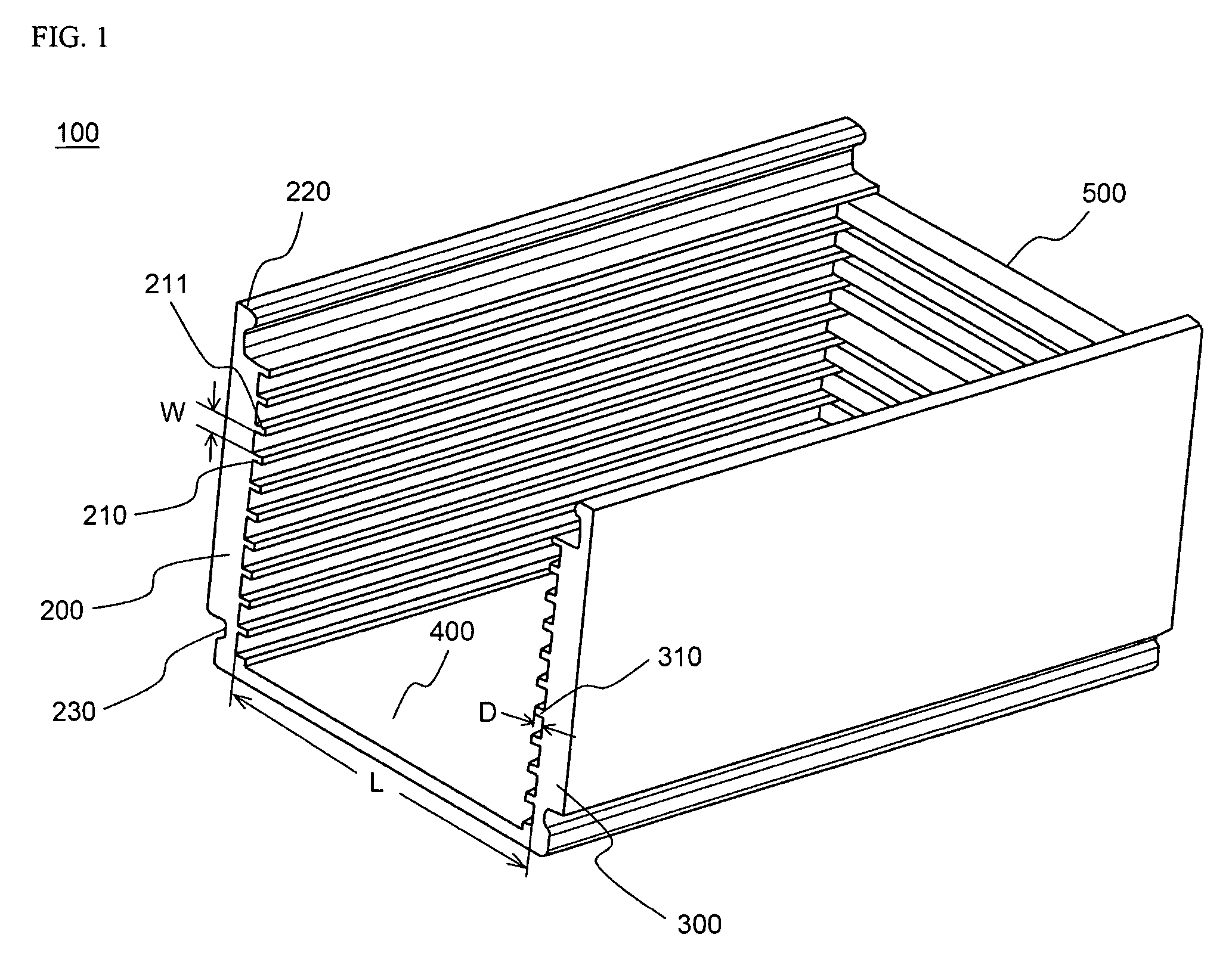
[0012] The width of the grooves corresponds to the thickness of each unit cell. However, the length of the grooves is not particularly restricted so long as the unit cells can be stably mounted between the right and left side members. In the battery module according to the present invention, the opposite sides of the unit cells are fixed at the side members, and the other regions of the unit cells are exposed. Consequently, the heat dissipation effect is very high, and therefore, desired heat dissipation is accomplished even though the distance between the unit cells is small, by which a high-density battery system can be manufactured.
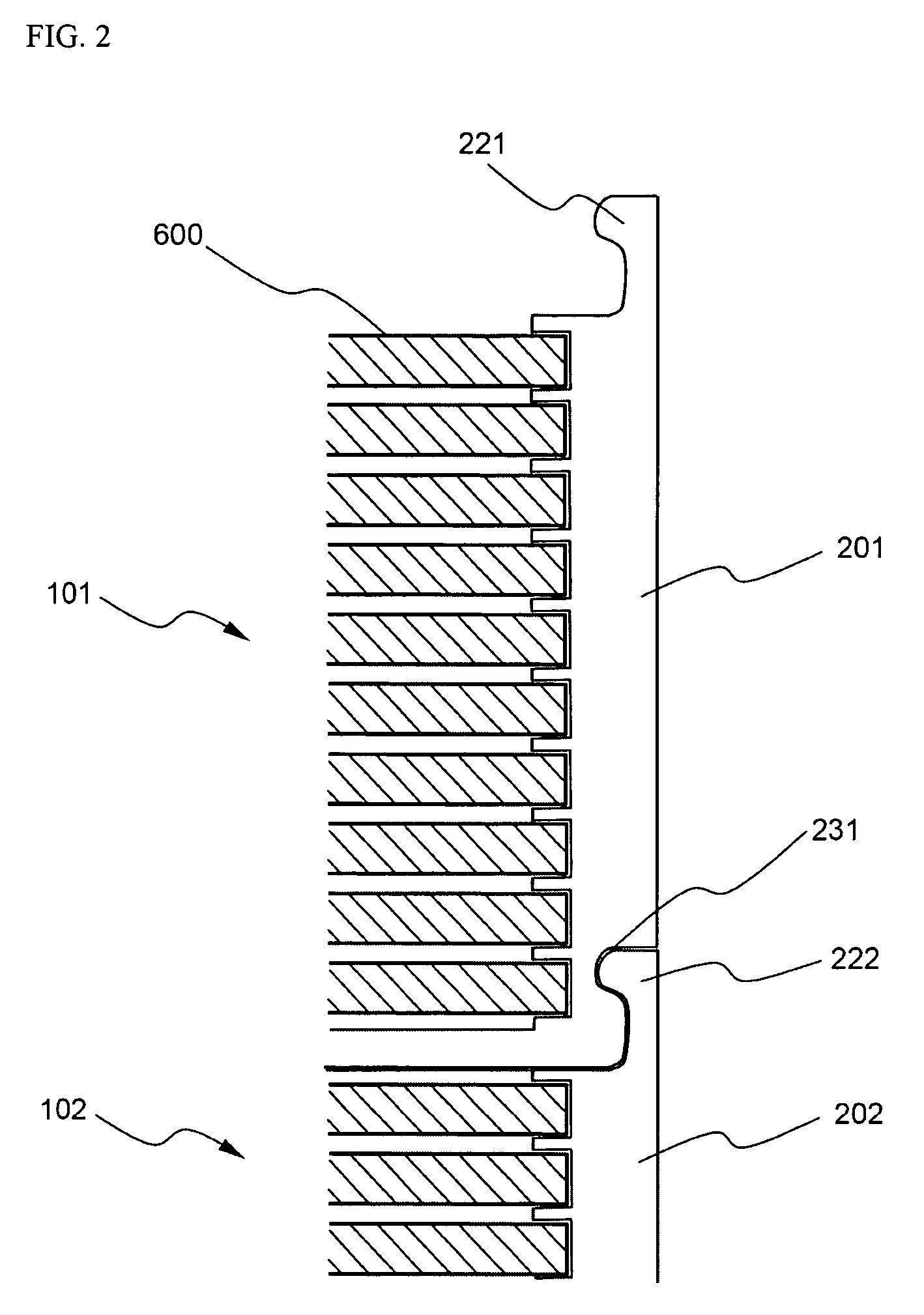
[0014] In a preferred embodiment of the present invention, the right and left side members are provided at the upper ends thereof with coupling protrusions, and the right and left side members are provided at the lower ends thereof with coupling grooves, which correspond to the coupling protrusions. Consequently, two or more battery modules can be easily coupled with each other. In the above-described structure, a plurality of battery modules can be coupled with each other in high density without using additional coupling members.
[0017] After the assembly of the battery module is completed, the electrode connection parts are electrically isolated from each other by the partitions. Consequently, a risk of an engineer or a user being exposed to electrical short-circuits is minimized, and a risk of electrical short-circuits due to external forces during the use of the battery module is greatly reduced.
[0022] Preferably, step (ii) includes: locating an insulating auxiliary member having slits, through which electrode leads of the unit cells are inserted, on the unit cells; and electrically connecting the electrode leads of the unit cells exposed above the auxiliary member, whereby the connection between the electrodes is more securely and easily accomplished. Preferably, the electrical connection between the electrodes is accomplished by positioning conductive bus bars on the electrode leads to be connected with each other and performing laser welding. Generally, the electrode leads are connected with each other by the laser welding, and therefore, the electrode leads have high reliability and stability. However, the unit cells may be damaged when cell bodies of the unit cells are exposed to a laser beam. According to the present invention, the above-mentioned problem is eliminated by the provision of the insulating auxiliary members as described above.
[0024] According to circumstances, the battery system manufacturing method further comprises the step of: mounting the above-described covering member at the electrode connection parts after step (ii) or step (iii), whereby a risk of the engineer or the user being exposed to the electrical short-circuits is minimized, and the electrical short-circuits between the electrode connection parts during the manufacture or use of the battery module is greatly reduced.

Problems solved by technology

Pouch-shaped lithium-ion polymer secondary cells, which are usually used as unit cells of a medium- or large-sized battery system, have low mechanical strength.
However, the cartridges are formed approximately in the shape of a plate, and therefore, the cartridges occupy a large amount of area.
Also, the protruding areas of a cathode and an anode of each unit cell are large, and therefore, an engineer who manufactures the battery system or a user may be exposed to a high risk of electrical short-circuits.
Furthermore, the electrical connection (in series or in parallel) between the electrodes is poor, and therefore, short-circuits may occur due to external forces, such as vibrations and impacts.

Method used


Image

  • Secondary battery module
  • Secondary battery module
  • Secondary battery module

Examples


Embodiment Construction

[0030] Now, preferred embodiments of the present invention will be described in detail with reference to the accompanying drawings. It should be noted, however, that the scope of the present invention is not limited by the illustrated embodiments.

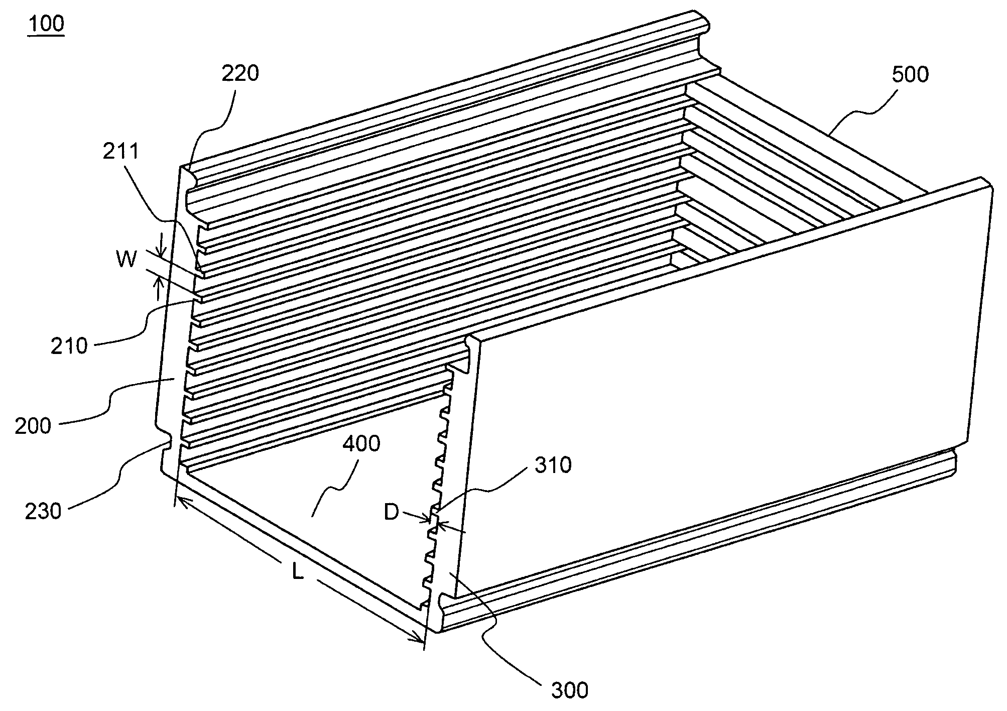
[0031]FIG. 1 is a typical perspective view illustrating a secondary battery module 100 according a preferred embodiment of the present invention.

[0032] Referring to FIG. 1, the battery module 100 is constructed approximately in a rectangular parallelepiped structure having an opened top part and an opened front part.

[0033] At a left-side member 200 and a right-side member 300 are formed grooves 210 and 310, respectively, which are arranged on the inside surfaces of the side members 200 and 300 such that the grooves 210 and 310 face each other. The distance between the side members 200 and 300 (more specifically, the distance between the grooves 210 of the left-side member 200 and the grooves 310 of the right-side member 300) is equal to ...


PUM

PropertyMeasurementUnit
widthaaaaaaaaaa
unit cellsaaaaaaaaaa
electrically insulatingaaaaaaaaaa

Abstract

Disclosed herein is a secondary battery module constructed approximately in a rectangular parallelepiped structure. The battery module includes a pair of side members (right and left side members) having pluralities of grooves formed at the inside surfaces thereof such that the sides of unit cells are securely fitted in the grooves and at least one connection member integrally formed with the side members such that the side members are spaced apart from each other by the width of the unit cells while the grooves of the side members face each other. A medium- or large-sized battery system is manufactured using one or more secondary battery module. The secondary battery module allows a plurality of unit cells to be mounted in the battery module with high density. Consequently, the total size of the battery system can be considerably reduced, and the electrical connection between the electrodes is highly stable. Furthermore, a risk of an engineer or a user being exposed to the electrical short-circuits is minimized, and a risk of electrical short-circuits due to external forces is greatly reduced.

Description

FIELD OF THE INVENTION [0001] The present invention relates to a secondary battery module, which has a plurality of unit cells, such as lithium-ion polymer secondary cells, mounted therein, and which is used to constitute a medium- or large-sized battery system, and to a method of manufacturing a battery system using the same, and, more particularly, to a secondary battery module having high density to minimize the volume of the battery system, having high stability to accomplish the coupling between electrodes, and minimizing a risk of a user being exposed to electrical short-circuits. BACKGROUND OF THE INVENTION [0002] Recently, a secondary battery, which can be charged and discharged, has been widely used as an energy source for wireless mobile devices. Also, the secondary battery has attracted considerable attention as a power source for electric vehicles and hybrid electric vehicles, which have been developed to solve problems, such as air pollution, caused by existing gasoline...

Claims


Application Information

Patent Timeline
Patent Type & Authority Applications(United States)
IPC IPC(8): H01M2/02H01M10/04H01M50/211H01M50/262H01M50/291
CPCH01M2/1077H01M2/24Y10T29/49108Y10T29/49114H01M10/0413Y02E60/10H01M50/529Y02P70/50H01M50/291H01M50/211H01M50/262H01M50/20H01M50/10
Inventor YOON, JUNILLRO, JONG-YULNAMGOONG, JOHN E.JUNG, DO YANG
Owner LG ENERGY SOLUTION LTD
Learn More