Blood-flow tubing

a technology of flow tubing and tubing nozzle, which is applied in the direction of bottles, containers, sensors, etc., can solve the problems that have not yet been shown whether angioscopic or not, and achieve the effect of reducing turbulence or reducing turbulen

Inactive Publication Date: 2007-12-06
TAYSIDE FLOW TECH
View PDF14 Cites 26 Cited by
  • Summary
  • Abstract
  • Description
  • Claims
  • Application Information

AI Technical Summary

Benefits of technology

[0011] The invention comprises, in one aspect, tubing, especially, but not exclusively artificial or modified natural blood f...

Problems solved by technology

However, even with this confirmation, it was admitted that it had not yet been shown whether angioscopic observations of...

Method used


Image

  • Blood-flow tubing
  • Blood-flow tubing
  • Blood-flow tubing

Examples


Embodiment Construction

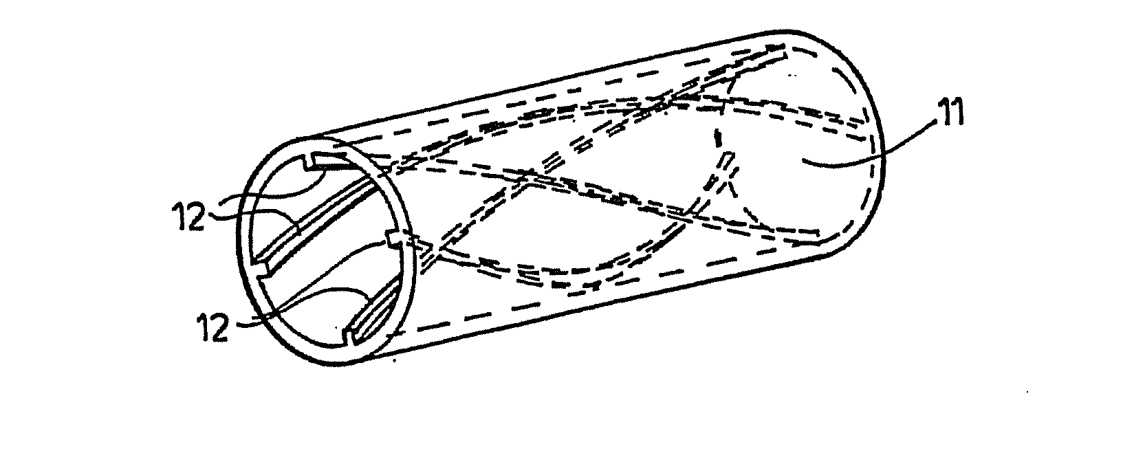
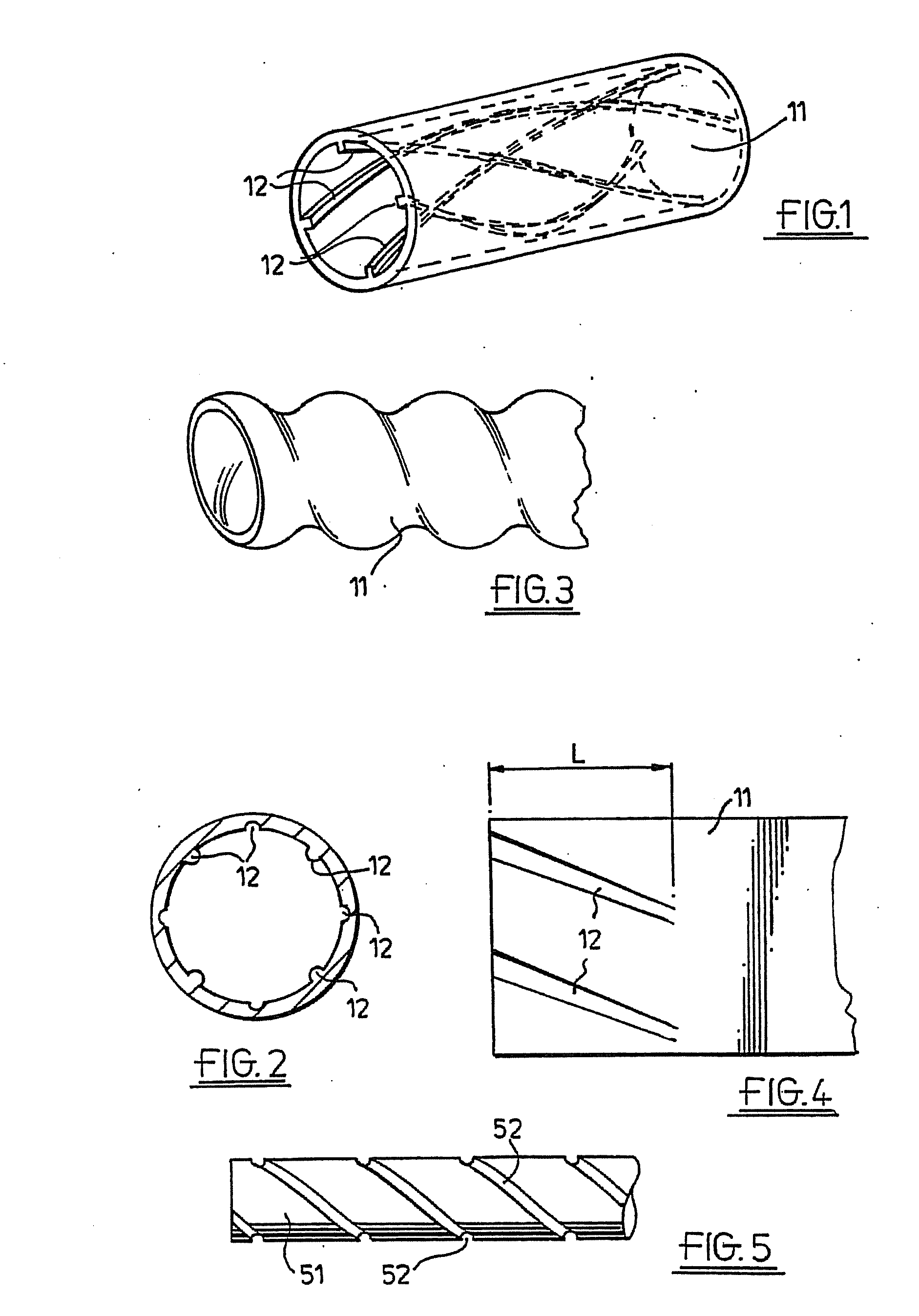
[0048] The drawings illustrate blood-flow tubing 11 having helical-flow inducing means 12 adapted to induce helical flow in such fashion as to eliminate or reduce turbulence. The tubing may be artificial, for example woven or knitted synthetic polymer fibre, in which the helical-flow inducing means may be knitted or woven structure as by three dimensional knitted or woven formation, or extruded or cast tubing, or modified natural, e.g. autograft material with an insert or with grooving made e.g. by a laser.

[0049] The helical-flow inducing means 12 may comprise grooving 14 and / or ridging 15, which may be multi-start grooving and / or ridging as seen in FIGS. 1, 2 and 4. Square-section ridging, as seen in FIG. 1, or grooving, or semi-circular section ridging and / or grooving, as seen in FIG. 2, can be used, but other cross-sections will serve as well, for example, triangular.

[0050] However, as seen in FIG. 3, a non-circular section tube 11 can have a twist, and may also have internal r...


PUM

PropertyMeasurementUnit
Timeaaaaaaaaaa
Angleaaaaaaaaaa
Angleaaaaaaaaaa

Abstract

An artificial or modified natural blood flow tubing has a helical-flow inducer to induce helical flow in such a fashion as to eliminate or reduce turbulence. One inducer is a tubular stent of expansible mesh having a helical vane.

Description

[0001] This application is a continuation of application Ser. No. 10 / 650,217, filed Aug. 9, 2003, which claimed priority to application Ser. No. 09 / 869,661, filed Jun. 29, 2001, which claimed priority from PCT No. PCT / GB99 / 04449, filed Dec. 23, 1999 which claimed priority from U.K. application Serial No. 9828686.6, filed Dec. 28, 1998.BACKGROUND [0002] 1. Field of the Invention [0003] This invention relates inter alia to artificial or modified natural blood-flow tubing, by which is meant artificial vascular prostheses or modified natural grafts or autografts, and tubing in which blood flows outside the body, e.g. in dialysis or in open heart surgery. Indeed, the invention might well extend to any tubing that carries a laminar flow, and particularly, but by no means exclusively, a pulsatile flow. [0004] 2. Description of the Related Art [0005] Spiral flow has been observed (Stonebridge P. A. and Brophy C. M., 1991, Spiral laminar flow in arteries? Lancet 338: 1360-61) during angiosco...

Claims


Application Information

Patent Timeline
IPC IPC(8): A61F2/06G01R33/48A61B5/055A61B8/06A61F2/86A61F2/90A61M1/14A61M5/14A61M25/00
CPCA61F2/06A61F2/86A61F2/90A61F2002/068A61F2230/0017Y10T428/1355Y10T428/1362Y10T428/1352Y10T428/1397Y10T428/139A61F2230/0091A61F2/844A61F2002/065
Inventor HOUSTON, JOHN GRAEMEDICK, JOHN BRUCE CAMERONSTONEBRIDGE, PETER
Owner TAYSIDE FLOW TECH
Why Eureka
Try Eureka