Conductive Endless Belt, Method For Producing Same, And Image Forming Apparatus Employing Same

a technology of endless belts and conductive materials, applied in the direction of instruments, coatings, pretreated surfaces, etc., can solve the problems of affecting the transfer efficiency, large and expensive apparatuses, and inability to obtain high image quality, and achieve fast, reliable curing, and stable production

Inactive Publication Date: 2007-12-13
BRIDGESTONE CORP
View PDF6 Cites 230 Cited by
  • Summary
  • Abstract
  • Description
  • Claims
  • Application Information

AI Technical Summary

Benefits of technology

[0032] In accordance with the present invention, an ultraviolet or electron beam curable resin is used as a constituent material of the resin layer provided on the belt base, which has enabled fast, easy, and reliable curing and formation of

Problems solved by technology

However, gradation control is very difficult in this system, so there is a problem that high image quality cannot be obtained.
This system provides a good image, but the apparatus is large and expensive because the four photoconductive drums each having an electrification device and a development device are disposed in series.
However, the resistance value of the resistive belt varies according to environment

Method used


Image

  • Conductive Endless Belt, Method For Producing Same, And Image Forming Apparatus Employing Same
  • Conductive Endless Belt, Method For Producing Same, And Image Forming Apparatus Employing Same
  • Conductive Endless Belt, Method For Producing Same, And Image Forming Apparatus Employing Same

Examples


examples 1-1 to 1-11

, Comparative Examples 1-1 and 1-2

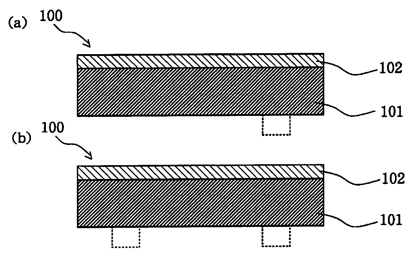
[0131] Conductive endless belts of Examples and Comparative Examples were made according to the formula listed in Tables 6 to 8. Specifically, the ingredients of the belt base listed in the tables were melt-kneaded using a biaxial kneader, and the thus obtained paste was extrusion molded using a ring-shaped dice to produce the belt base 101 having an inside diameter of 220 mm, a thickness of 100 μm, and a width of 250 mm. Thereafter, a solvent-free resin layer coating liquid composed of the ingredients listed in the tables was applied to the belt base 101 using a roll coater in a film thickness listed in Tables 9 to 11. With rotating the coated belt 100, the coating of the resin layer 102 was irradiated with ultraviolet light for curing using UNICURE UVH-0252C (manufactured by Ushio Inc.) at an illumination of 400 mW and a cumulative luminous energy of 1000 mJ / cm2, thus the conductive endless belt 100 was obtained. The resin layer 102 was not formed...

examples 2-1 to 2-11

, Comparative Examples 2-1 and 2-2

[0143] Conductive endless belts of Examples and Comparative Examples were made according to the formula listed in Tables 12 to 14. Specifically, the ingredients of the belt base listed in the tables were melt-kneaded using a biaxial kneader, and the thus obtained paste was extrusion molded using a ring-shaped dice to produce the belt base 101 having an inside diameter of 220 mm, a thickness of 100 μm, and a width of 250 mm. Thereafter, a solvent-free resin layer coating liquid composed of the ingredients listed in the tables was applied to the belt base 101 using a roll coater in a film thickness listed in Tables 12 to 14. With rotating the coated belt 100, the coating of the resin layer 102 was irradiated with electron beams for curing using Min-EB (manufactured by Ushio Inc.) under conditions of an applied voltage of 30 kV, a tube current of 300 μA, an irradiation distance of 100 mm, a nitrogen atmosphere of 760 mmTorr, and an irradiation time of ...


PUM


Abstract

Provided are a conductive endless belt, a method of producing the same, and an image forming apparatus employing the same, the conductive endless belt having both desirable intended belt properties and surface properties, and being producible without known problems in terms of cost and quality.
A conductive endless belt 100 is used as a transfer/transport conductive endless belt for a tandem system in which the conductive endless belt is circularly driven by a drive member so as to transport a recording medium held by the belt through electrostatic attraction to four differing image forming bodies, in which the toner images are sequentially transferred onto the recording medium. The conductive endless belt 100 is composed of a belt base 101 having thereon a resin layer 102, the resin layer 102 containing an ultraviolet or electron beam curable resin. The resin layer 102 preferably contains a conductive agent, specifically carbon black.

Description

TECHNICAL FIELD [0001] The present invention relates to a conductive endless belt (hereinafter may be simply referred to as “belt”), a method of producing the same, and an image forming apparatus employing the same, the conductive endless belt being used for transferring a toner image onto a recording medium such as paper in an electrostatic recording process performed in an electrophotographic apparatus or electrostatic recording apparatus such as a copy machine or printer, the toner image being formed by supplying a developer onto the surface of an image forming body such as a latent image holder holding a latent image thereon. BACKGROUND ART [0002] Heretofore, in an electrostatic recording process performed in, for example, a copy machine or printer, printing has been carried out by the steps of uniformly electrifying the surface of a photoconductor (latent image holder), forming an electrostatic latent image by projecting an image from an optical system onto the photoconductor t...

Claims


Application Information

Patent Timeline
IPC IPC(8): B29D29/00G03G15/16
CPCB29D29/00G03G2215/0177G03G2215/0119G03G15/1685G03G15/01
Inventor SUZUKI, TAKAHIROMACHIDA, KUNIOTAKAGI, KOJI
Owner BRIDGESTONE CORP
Why Eureka
Try Eureka