Heat transfer for ocean thermal energy conversion

a technology of heat transfer and ocean thermal energy, applied in sea energy generation, machines/engines, mechanical equipment, etc., can solve the problems of large heat release, inability to have a wick, and inability to achieve heat dissipation

Inactive Publication Date: 2007-12-20
PRUEITT MELVIN L
View PDF5 Cites 57 Cited by
  • Summary
  • Abstract
  • Description
  • Claims
  • Application Information

AI Technical Summary

Benefits of technology

[0007]It is therefore an object of the present invention to provide a means of moving large quantities of heat from the top of an OTEC plant to the location of cold water deep in the ocean by using evaporation of a fluid, conducting the fluid from the ocean surface to deep ocean, and condensing the fluid.
[0008]It is another object of the present invention to increase the efficiency of an OTEC plant by its method of transferring heat in heat exchangers at constant temperatures.
[0009]It is another object of the present invention to eliminate the energy requirements of pumping large quantities of cold seawater to the surface.

Problems solved by technology

Since it would not be practical to have a wick transport the liquid for a kilometer of vertical distance, the heat pipe described herein will pump the liquid to the surface.
The vapor then flows down the pipe to the bottom, where it condenses and releases large quantities of heat.

Method used


Image

  • Heat transfer for ocean thermal energy conversion
  • Heat transfer for ocean thermal energy conversion
  • Heat transfer for ocean thermal energy conversion

Examples


Embodiment Construction

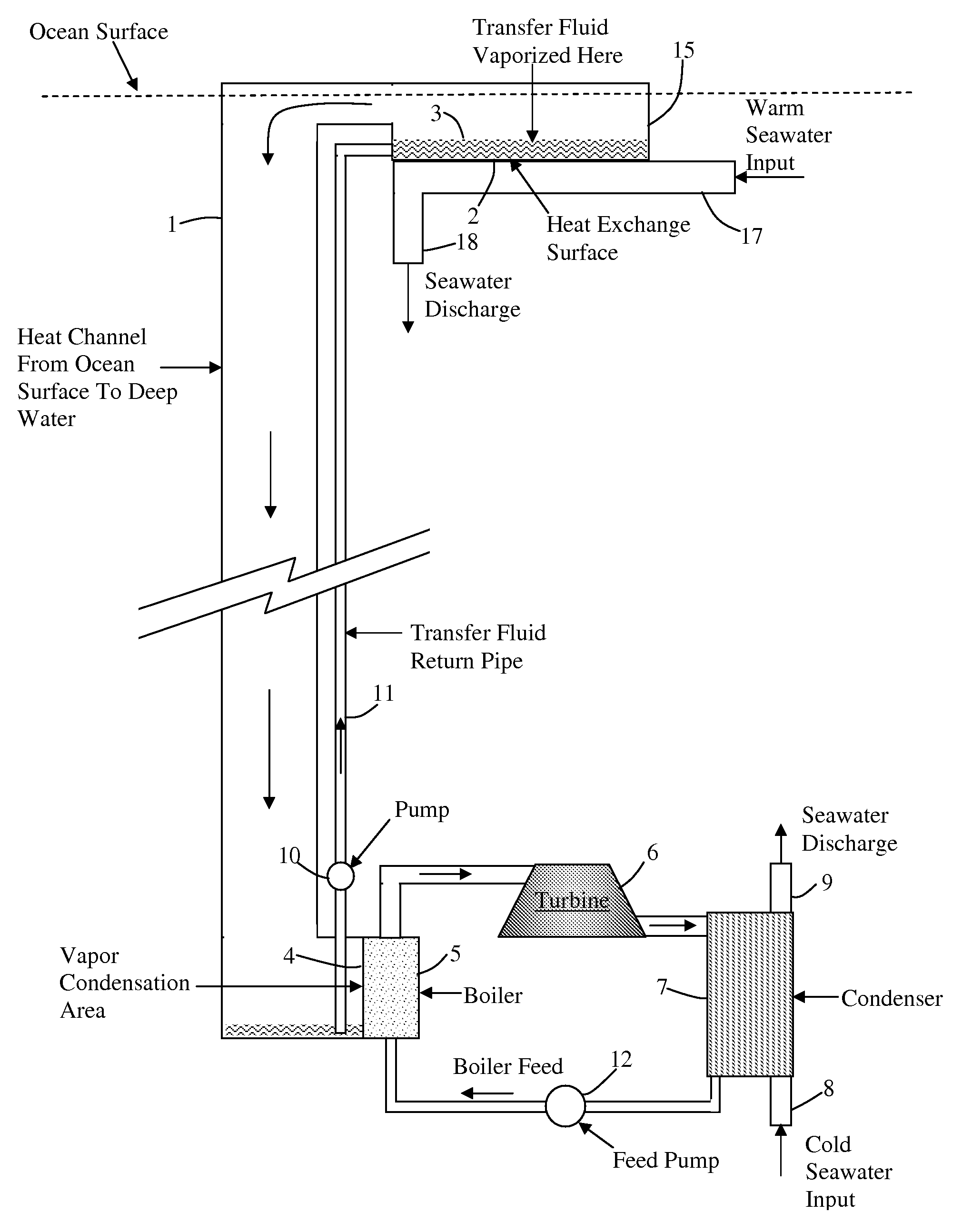
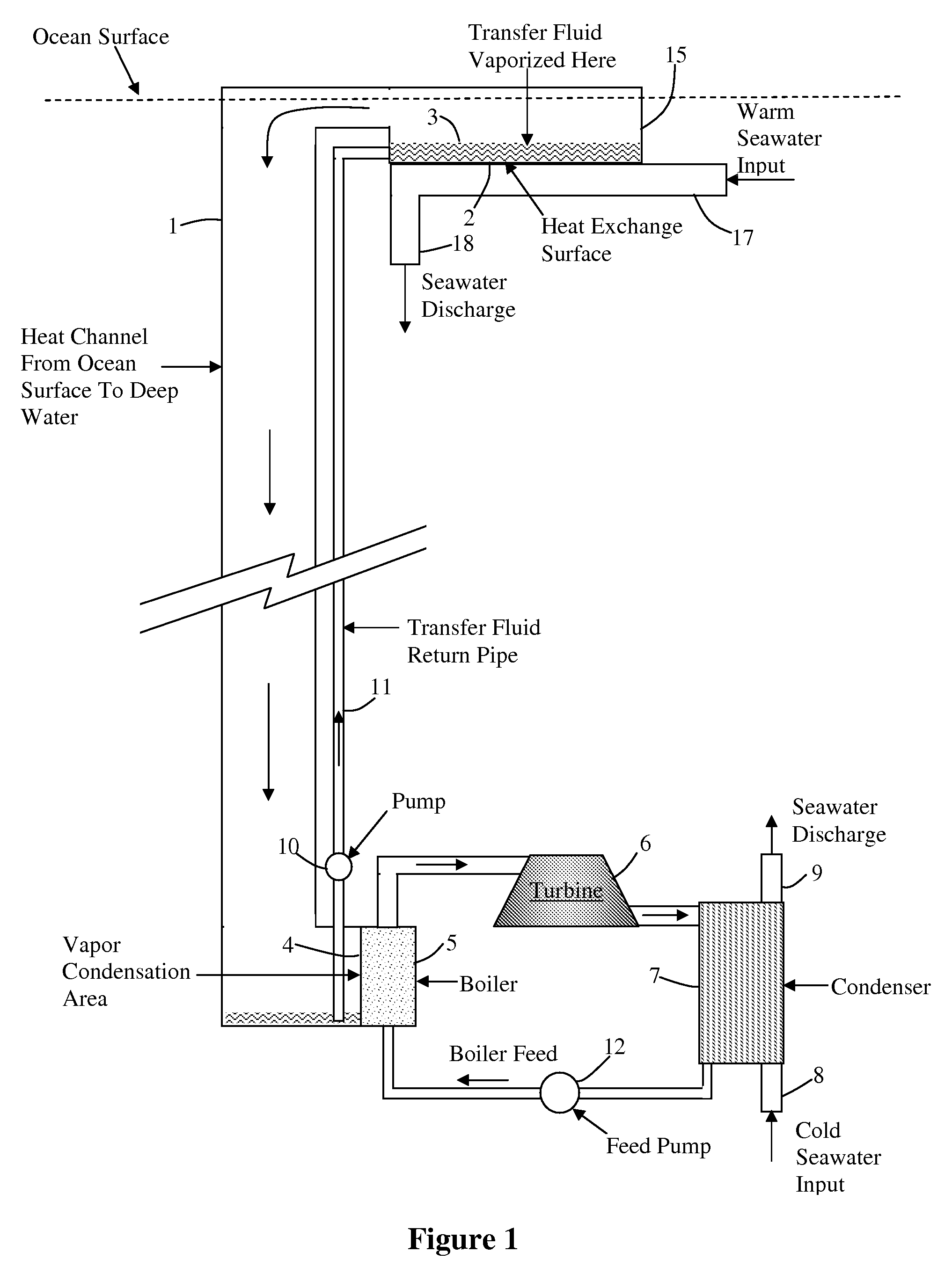
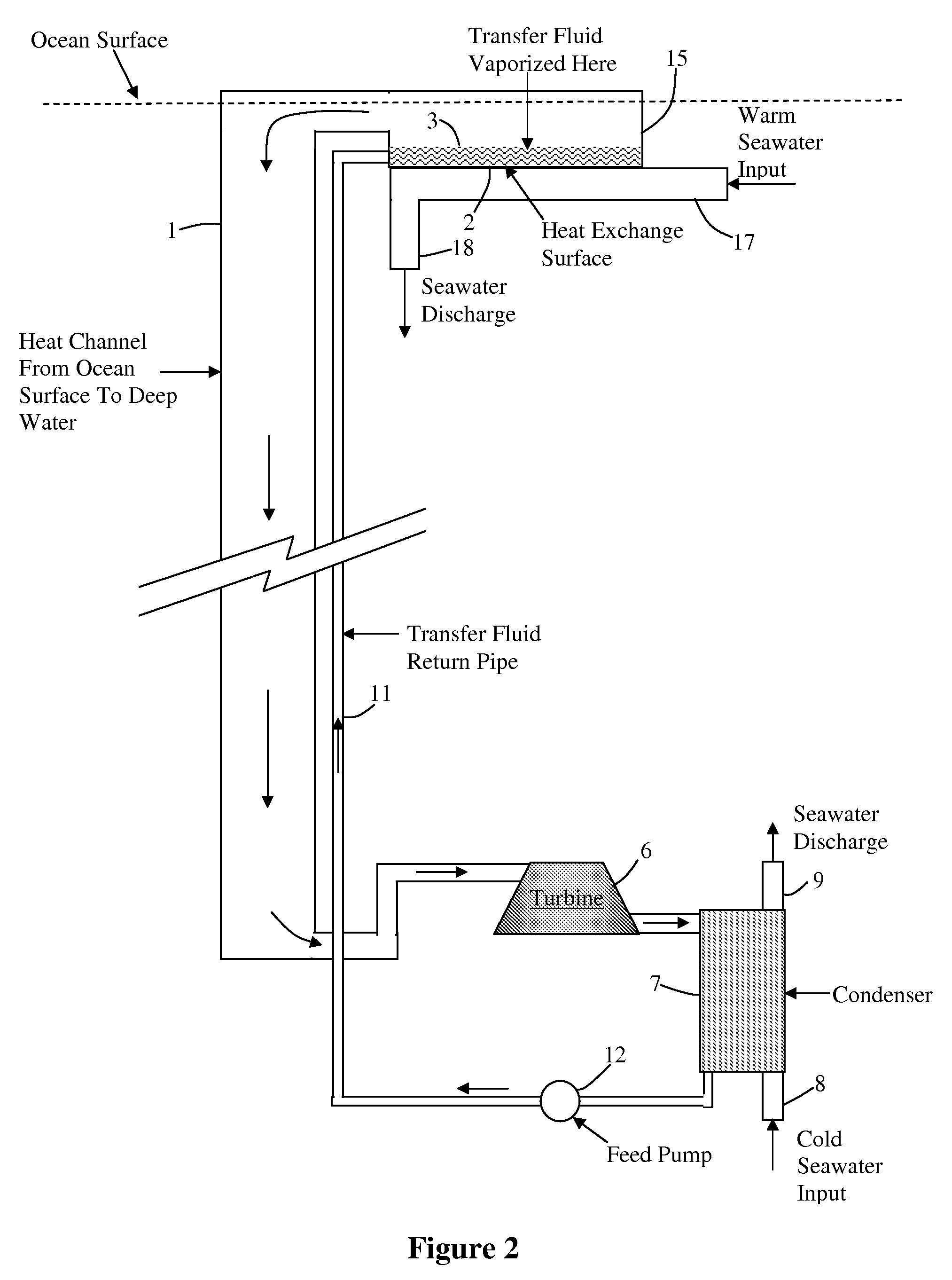
[0016]Let us first consider a design in which the turbines, generators, and heat exchangers are at 1,000-meter depth. (Later we will look at the design which has the turbine and generator at the surface). FIG. 1 gives a schematic presentation of the design. At the ocean surface, warm seawater entering pipe 17 is pumped through a heat exchanger or simply moved across a heat exchange surface 2 on the bottom of an evaporation tank 15 that transfers heat into a heat transfer liquid 3 that evaporates and carries the latent heat of evaporation down the heat channel 1 to a depth of 1,000-meters. It should be understood that the heat transfer can be done with a heat exchanger that has many heat transfer surfaces. The drawing of FIG. 1 presents the concept with a single surface for simplicity.

[0017]At the bottom, the vapor condenses on a heat exchange surface 4 (or in a heat exchanger) and transfers heat into a working fluid in a boiler 5, and the working fluid drives a turbine 6 to produce ...


PUM


Abstract

For OTEC (Ocean Thermal Energy Conversion), rather than transfer huge quantities of cold water from deep in the ocean to the surface to provide a heat sink for a heat engine or for desalination, this invention provides a method of using small masses of low-boiling-point fluids to absorb heat in a heat exchanger near the ocean surface using the latent heat of evaporation and then depositing the latent heat of condensation in a deep ocean heat exchanger, using the cold seawater as a heat sink. The condensed liquid is pumped back to the ocean surface. The heat engine (turbine) and generator can be at the ocean surface, or it can be in deep ocean. By using a fluid that transfers heat by evaporation and condensation, much larger quantities of heat can be moved per kilogram of fluid than can be transferred by moving the same mass of seawater.

Description

CROSS-REFERENCE TO RELATED APPLICATION[0001]This claims priority to and the benefit of Provisional U.S. patent application Ser. No. 60 / 804827, filed Jun. 15, 2006, the entirety of which is hereby incorporated herein by reference.BACKGROUND OF THE INVENTION[0002]Using the temperature differential between the surface of the tropical ocean and the water 1,000 meters down is an important way to provide abundant electrical power. The Ocean Thermal Energy Conversion (OTEC) method uses the warm surface water to boil a working liquid to produce a vapor that drives a turbine, and it pumps cold water from the dark depths to the surface to condense the vapor after it leaves the turbine. A 100 MW OTEC plant would require 200 cubic meters of cold water per second flowing up through a 11 meter (36 foot) diameter pipe. Since the cold water is denser than the surrounding water, just lifting the extra weight of the water would require about 3.5 MW of power. The resistance to the flow due to the visc...

Claims


Application Information

Patent Timeline
Patent Type & Authority Applications(United States)
IPC IPC(8): F03G7/05
CPCY02E10/34F03G7/05Y02E10/30
Inventor PRUEITT, MELVIN L.
Owner PRUEITT MELVIN L
Why Eureka
Try Eureka