Heat Shield Element, Method and Mold for the Production Thereof, Hot-Gas Lining and Combustion Chamber

a heat shield element and mold technology, applied in continuous combustion chambers, machines/engines, printing, etc., can solve the problems of affecting the service life forming cracks, and temperature gradients in the edge region of heat shield elements, so as to reduce tolerances, reduce labor intensity, and remove heat shield elements with ease

Inactive Publication Date: 2007-12-20
SIEMENS AG
View PDF12 Cites 16 Cited by
  • Summary
  • Abstract
  • Description
  • Claims
  • Application Information

AI Technical Summary

Benefits of technology

[0040] If the mold is composed of a plurality of individual parts which for the pouring-in process have to be tightly connected to one another to form the single-piece mold shell, it is possible, by detaching the individual parts from one another, to remove the cured heat-shield element with ease.
[0041] In contrast to the mold according to the prior art in which one side of the mold is completely absent during the pouring in, in the mold according to the invention a mold surface with a pouring-in aperture for feeding the mold is present. In other words, the mold surface in which the pouring-in aperture is located defines the corresponding surface of the heat-shield element at least in a rudimentary manner. With the mold according to the invention, all the surfaces of the heat-shield element can therefore be shaped at least in a rudimentary manner without the need for compression-molding of the heat-shield element. The mold surface present in rudimentary form in the area of the pouring-in aperture results here in surplus casting material present in the area of the entry aperture can be removed after the curing with the aid of the rudimentary heat-shield element surface formed by the mold surface as a reference surface. The removal of surplus material and the finishing of the heat-shield element are therefore possible with relatively little effort.
[0042] Moreover, the dimensions of the cast heat-shield element depend when the mold according to the invention is used not on the quantity of material poured in, since no compression molding is carried out. Since in the compression-molding process according to the prior art, the mold is fully closed, there is no possibility of the casting material escaping from the mold. Varying quantities of casting material therefore lead to the production of heat-shield elements of differing thickness. In the mold according to the invention, by contrast, surplus casting material can escape through the pouring-in aperture without thereby interfering with the dimensions of the heat-shield element. Furthermore, no springing back of the mold under compressive pressure occurs during casting. The mold according to the invention therefore enables the production of heat-shield elements with reduced tolerances.

Problems solved by technology

Air which simultaneously serves as cooling air for cooling the retaining brackets holding the heat-shield elements is generally used as sealing air, and this leads among other things to the occurrence of temperature gradients in the region of the edges of a heat-shield element.
Therefore, in ceramic heat-shield elements in particular, even where adjacent heat-shield elements do not touch one another, stresses can occur on the hot side which can lead to cracking and can thus adversely affect the service life of the heat-shield elements.
This tension can, where the tensile strength of a material is exceeded, lead to the formation of cracks which emanate from the edges of the heat-shield element and run toward central areas of the heat-shield element.
The thermally induced cracks can lengthen as a result of mechanical strains arising during operation of the gas-turbine plant, which leads to a further reduction of the residual cross section and may make the replacement of the heat-shield element necessary.
The introduction of flow barriers is not, however, always readily possible and also increases the complexity of a heat shield.
While metal heat-shield elements exhibit greater resistivity to temperature fluctuations and mechanical loadings than ceramic heat-shield elements, they necessitate, in gas-turbine combustion chambers for example, costly cooling of the heat shield since they have a higher thermal conductivity than ceramic heat-shield elements.
Moreover, metal heat-shield elements are more susceptible to corrosion and, on account of their lower temperature stability, cannot be exposed to such high temperatures as ceramic heat-shield elements.

Method used


Image

  • Heat Shield Element, Method and Mold for the Production Thereof, Hot-Gas Lining and Combustion Chamber
  • Heat Shield Element, Method and Mold for the Production Thereof, Hot-Gas Lining and Combustion Chamber
  • Heat Shield Element, Method and Mold for the Production Thereof, Hot-Gas Lining and Combustion Chamber

Examples


second embodiment

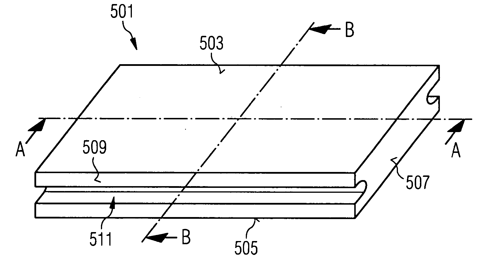
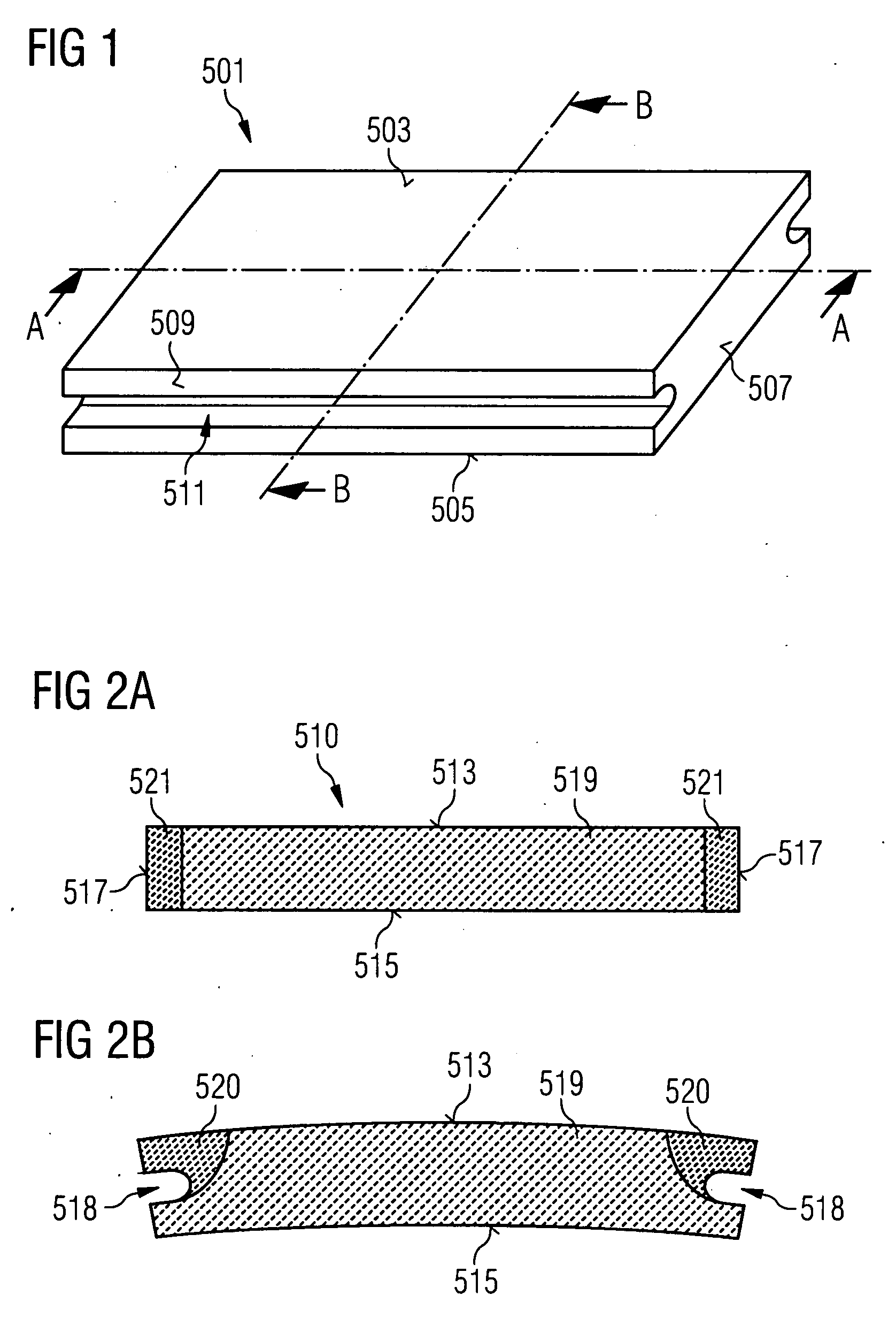
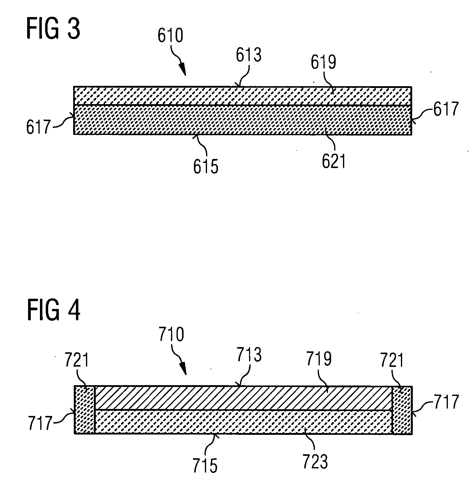
[0081] the heat-shield element according to the invention is shown in section in FIG. 3. The section runs along the line A-A shown in FIG. 1. Correspondingly, the hot side 613, the cold side 615 and the ungrooved peripheral surfaces 617 of the heat-shield element 610 can be seen.

[0082] The heat-shield element 610 has on the hot side a material zone 619 with a relatively low coefficient of thermal expansion and / or relatively low thermal conductivity. On the cold side, it has a material zone 621 with, relative to the material zone 619 on the hot side, an increased coefficient of thermal expansion, increased thermal conductivity and / or increased mechanical loading capacity. Furthermore, the material of the material zone on the cold side is chosen such that it possesses a greater rigidity than the material of the material zone on the hot side. Less emphasis needs to be placed on the thermal resistivity of the material zone on the cold side than on the thermal resistivity of the material...

third embodiment

[0088] the heat-shield element according to the invention is shown in section in FIG. 4. The section runs along the line A-A shown in FIG. 1. Correspondingly, the cold side 713, the hot side 715 and the ungrooved peripheral surfaces 717 of the heat-shield element 710 can be seen. The heat-shield element 710 has a first material zone 719 on the hot side with a first coefficient of thermal expansion, second material zones 721 on the peripheral sides with a second coefficient of thermal expansion and a material zone 723 on the cold side with a third coefficient of thermal expansion. The second and the third coefficients of thermal expansion can also be identical. Through appropriate choice of the coefficients of thermal expansion of the individual material zones, stresses which arise due to temperature gradients in the interior of the heat-shield element 710 can reliably be minimized. The material zones can also have different rigidities.

[0089] Further combinations of material zones wi...


PUM

PropertyMeasurementUnit
coefficients of thermal expansionaaaaaaaaaa
operating temperaturesaaaaaaaaaa
rigidityaaaaaaaaaa

Abstract

There is described a heat shield element comprising a hot side which is turned towards the hot medium, a cold side which is turned away from the hot medium, peripheral sides which connect the hot side to the cold side and a material volume which is defined by the hot side, the cold side and the peripheral sides, wherein the material volume comprises at least two material areas which are made of different materials. The materials are different from each other at least in respect of their resistance and/or thermal expansion coefficient.

Description

CROSS REFERENCE TO RELATED APPLICATIONS [0001] This application is the US National Stage of International Application No. PCT / EP2005 / 012447, filed Nov. 21, 2005 and claims the benefit thereof. The International Application claims the benefits of European application No. 04028445.7 EP filed Dec. 1, 2004, European application No. 05014376.7 EP filed Jul. 1, 2005, and European application No. 05014798.2 EP filed Jul. 7, 2005, all four of the applications are incorporated by reference herein in their entirety.FIELD OF INVENTION [0002] The present invention relates to a heat-shield element, in particular a ceramic heat-shield element, a method for the production of a ceramic heat-shield element, a hot-gas lining constructed from heat-shield elements and a combustion chamber equipped with a hot-gas lining, which combustion chamber can be embodied in particular as a gas turbine combustion chamber. The invention also relates to a mold for the production of a ceramic heat-shield element. BAC...

Claims


Application Information

Patent Timeline
Patent Type & Authority Applications(United States)
IPC IPC(8): F23R3/00B28B7/00C04B35/64
CPCB28B1/16B28B7/0014B28B7/0079B28B23/0056F23M5/02F23M2900/05004C04B2235/6027C04B35/1015C04B35/117C04B35/565C04B2235/3418C04B2235/3463C04B2235/602F23R3/007
Inventor GROTE, HOLGERHEILOS, ANDREASTERTILT, MARC
Owner SIEMENS AG
Why Eureka
Try Eureka